Ah ha! Thanks for explaining the truck suspension. I always wondered how they done that. I know that older locomotives mounted the engine (drive wheels) to the boiler without a full frame. That’s a detail I need to work out on a model I may eventually get back to. And I also knew them older locomotives used oil cups, and left some oil drips everywhere they went. The whole narrative and pictures you are posting is very informative. Thanks for sharing.
Eric
Keep us informed.
I’m really enjoying looking and reading the progress.
And to think that the Portland Co. (next to the museum ) built this beauty!
Is it done yet? (http://largescalecentral.com/externals/tinymce/plugins/emoticons/img/smiley-laughing.gif)(http://largescalecentral.com/externals/tinymce/plugins/emoticons/img/smiley-innocent.gif)(http://largescalecentral.com/externals/tinymce/plugins/emoticons/img/smiley-cool.gif)
I had to beat Rooster to it.
OK so what are Eames Vacuum Brakes? How do they work.

This is the vacuum ejector or “pump” When the the engineer wants brakes, He pulls that lever which opens a valve that shoots steam though a venturi. the venturi is set up so that it pulls air into the steam stream and ejects it up the exhaust. that air comes from the brake system making a vacuum in that system. the amount of steam can be regulated and thus the amount of vacuum.

the top gauge is for the vacuum.

this is one of the vacuum “pots” which actuates the brakes. There are three of these on #9. one for the rear truck, and one for each side of the driver brakes. the driver brakes were added to the locomotive by the WW&F shop in the '30s and were not seen on most Portland Company Forneys.
The conical part marked “EAMES” is a Diaphragm. when a vacuum is applied through the pipe, the diaphragm collapses and draws the eyebolt inward with considerable force. a chain and linkage is attached the eye bolt to the brake rigging.

I made the diaphragms for the locomotive. the one in the photo is one of the first. it has a bunch of bubbles but is certainly serviceable. It consists of 2 layers of heavy canvas saturated in urethane rubber.

a freind made the first part of the mold. I polished it and epoxy coated it, then made a mating mold so that we could squeeze the canvas between them.

We roughly sew two “preforms” of canvas, then brush them liberally with the urethane then stick them in a mold.

this is a the mold in process and one completed diaphragm on the right. It will need holes drilled for mounting bolts but is otherwise ready to go.
Excellent work Eric on both the description of the Eames system as well as the work on making the diaphragms.
If I could add to the Eames system the exhaust plumbing from the ejector was plumbed several different ways. The first was to exhaust it through a straight pipe in the roof. However this was very loud and screechy. They then tired to add mufflers to it. I have seen pictures of both of those. Another way I have heard of was to exhaust into the ash pan but I have not seen this and I would think that wouldn’t be very practical so I don’t really know. The later way, and I believe the better way, was to exhaust it to the smoke box and out the stack. Here is a picture of the CR&N #4 which is the EBT #9.
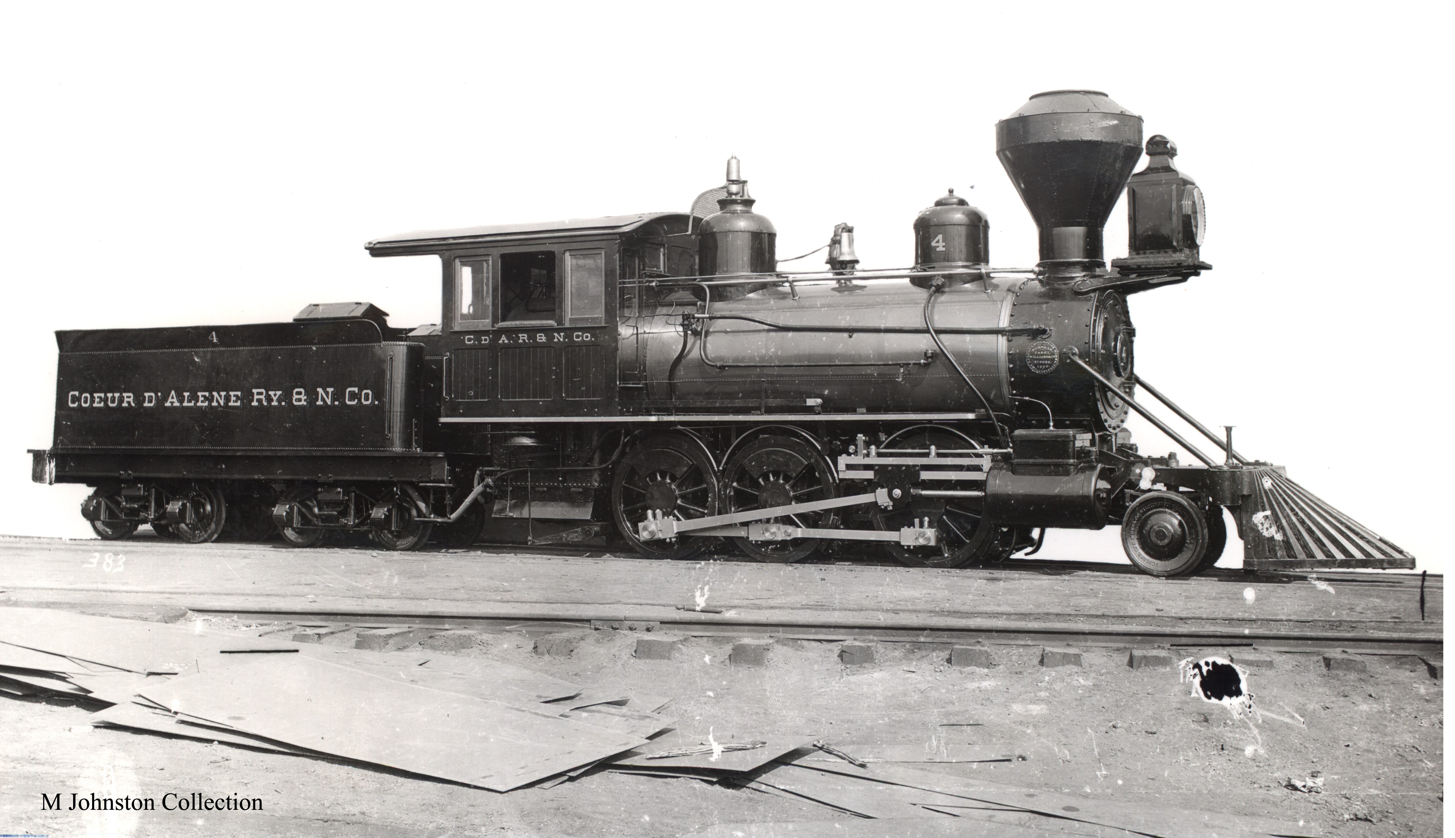
If you look you can see the Eames ejector (yes its an ejector not an injector) just forward of the cab. ( The #4’s boiler took up so much room in the cab that they moved it outside). Then there is a pipe leading to the smoke box that’s the exhaust. The pipe coming in from the cab is connected to the manifold (likely) and is the steam supply. The pipe going through the running board is the vacuum line and goes down and tees to the actuator (pot) and then back to the tender and so forth on back provided the equipment was so equipped.
The Eames system was purported to have superior breaking capability over the pressure system. The vacuum was more uniform over a long train than pressure systems meaning more equal breaking. The killer was that it required a positive vacuum to apply the breaks. In a zero vacuum state the breaks were off. Where as a positive pressure system used pressure to hold the breaks off and reduction in pressure to apply the breaks. So positive train breaking requirements spelled death to the Eames. When the cars disconnect with the Eames you have a run away as opposed to applied breaks.
Now that’s how I understand it. I am no expert so please chime in if I am mistaken.
Our engine has tried all those options. The WW&F had the exhaust sticking straight up…we’ll see what we think of that in a little while
Portland Company built the engine with the exhaust going into the smokebox (and up the stack?)

it is a little hard to see but the ejector exhaust pipe runs down and forward to the smokebox in this photo of her brandy new.

Here you can see the exhaust has been moved to the ash pan. the original location is visible as a round patch behind the running board below the clean out hatch. this photo pretty closely follows Jayson’s plan for the Accucraft engine. She changed a lot over the years.

At some point the SR&RL moved the exhaust to the front top of the cab…with a muffler which looks like a coffee can. here she is in Kennebec Central service
My understanding of the story about Eames…
He developed the vacuum brake system shown here. Yes it was well liked. two difficulties were that if cars became disconnected from the brake line they would have no brakes and it didnt work well on long trains as a vacuum had to created throughout the train…more cars the longer it took. there were probably different size ejectors.
As I understand it, Eames was developing an automatic system which would apply brakes if the connection between engine and cars was severed. This system was similar to the direct system on #9 but had a small reservoir to hold vacuum and an enclosed double acting diaphragm. as with the Westinghouse system the engine would pump (down) the train before it could move. vacuum had to be maintained in the system to run, less vacuum applied brakes. The WW&F will be installing and testing this system (as interpreted) shortly.
Eames’s company had been in financial difficulties and he was locked out. he had resolved the issues and was attempting to re-enter the factory when he was shot dead (while breaking in to his own shop?) That ended that, and Westinghouse won! The British used Vacuum brakes until fairly recently (they run/ran shorter trains typically)
Well now I can say I have seen it exhausted into the ash pan now. As for the in the smoke box application as far as I know it did not run up the stack just into the smoke box itself and let the smoke and steam do its thing. My understanding was this made for an excellent muffler basically eliminating all the noise. Since my little RR used the Eames system exclusively i am fascinated by it.
I will be curious to hear how you guys fair with the noise. My understanding is it is a very loud screeching sound if un-muffled. So I will be curious as to how you guys do it and what you thin of the noise level. Is the choice to muffle it as opposed to running it to the smoke box a practical thing or a authenticity thing?
David Maynard said:
The whole narrative and pictures you are posting is very informative. Thanks for sharing.
I agree with David. Enjoying this thread a lot.
Duplicate post deleted.
It seems the Sandy River quite quickly moved the exhaust from the smoke box… Must not have been that great for some reason… Likewise away from the ash pan. The WW&F was too broke by the end to deal with any mufflers… The just ran the pipe straight up even on their other engines.
Back to the trailing trick. I meant to ask but we got side tracked. I get how it swings side to side but what actually holds it on. At least on the pilot trucks I am used to there is an arm that runs back and attaches to a pivot point. I can’t see what hold the truck on. It can’t just rest on it.
The loco just rests on the rear truck at the pivot point. safety chains keep it near in case of derailment. there is no radius bar which would only be necessary with one axle which cannot keep itself aligned.
It is interesting, the springs are pinned to the truck but the pivot just rests atop the hard point on the springs and the loco rests on that…no bolts!
Eric Schade said:
The loco just rests on the rear truck at the pivot point. safety chains keep it near in case of derailment. there is no radius bar which would only be necessary with one axle which cannot keep itself aligned.
It is interesting, the springs are pinned to the truck but the pivot just rests atop the hard point on the springs and the loco rests on that…no bolts!
That is interesting. I would never have imagined it just sat on it. But the pivot bar on a single axle truck would make sense to keep it aligned and not necessarily attached. Thanks.
Eric Schade said:
The loco just rests on the rear truck at the pivot point. safety chains keep it near in case of derailment. there is no radius bar which would only be necessary with one axle which cannot keep itself aligned.
Just to digress/elaborate slightly . . many trolley trucks have that same ‘swing linkage’. It seems to go along with rough track!
This is a Brill trolley truck, photographed a couple of years ago in Scranton. The plates with the 3 bolts on top of the sideframe hold the cross-beam (bottom of it visible under the top frame member.) What is more visible are the drop links and bottom pivots for the swing frame that the springs - and body pivot - rest on.

I know all this because I’ve been producing CAD drawings of EBT’s M-1 gas-electric railcar. It uses the same swing pivot trucks (bought from Brill, I believe,) though the swing links are harder to see. This photo, taken when the truck was off the car for maintenance, almost shows the top pivot links, just like WW&F #9. What is clearly visible is the heavy frame with the pivot that reaches down to the bottom of the 4 springs.

It is interesting, the springs are pinned to the truck but the pivot just rests atop the hard point on the springs and the loco rests on that…no bolts!
I guess that is insurance for when the curve is tighter than the truck was designed for. Worst case it will move completely off the pads (shown in your other photo of the swing link) and bump into the swing pivot rod. When the loco straightens up, it will be forced back onto the pads and all will be well. I would suspect that the distance from the pad to the pivot rod is less than the width of the pivot plate, so it can’t drop entirely off the pads?
Pete,
If you posted photos, they did not show up!
*After adjusting Ghostery settings they show up. VigLink was being blocked and blocking the pictures.
I see them
Amazing to see one of these old locos being brought back to life.
I thought it might be fun to talk about some of the sub projects I worked on…
The original whistle had gone missing some time in the '30s so we had castings made for a new one. I go the job of machining the raw castings into a new whistle.

these are the raw castings.

I used the shop’s lathe to do the machining. this is the base…valve body.
more to follow…
Eric ,
I did see a pic of your one volunteer in the back of trains magazine recently “grinding in the boiler” . The last pages with the pics is usually my favorite of that magazine!