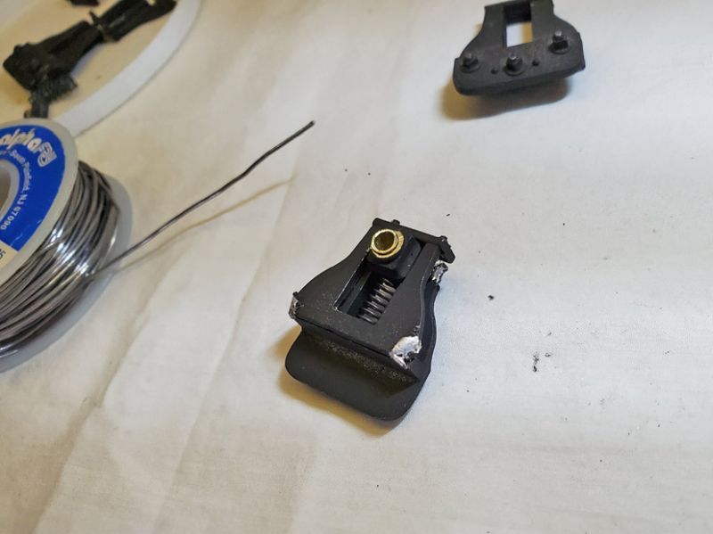
I had these (whatever they are called) switched to the wrong side when I put everything back together.
They are called bearing blocks, or hornblocks. They slide up and down in a slot in the frame and hold the axles in the right place. On top is a spring that helps the wheel drop into a low point on the track to keep all 4 wheels in contact.
And yes, you do have to get them back in the same side they were when you started. (http://www.largescalecentral.com/externals/tinymce/plugins/emoticons/img/smiley-wink.gif)With the springs in place.
For background, let me offer a quick dissertation on bearing springs. There are 2 schools of thought in our model world: either put in weak springs and let the bearing blocks ride at the top of the chassis/frame slot, or put in strong springs so the bearing block does not hit the top of the slot and rides on the springs. The former is easier to make and works by forcing that side of the axle to drop when necessary due to rough track. The second version is more prototypical and theoretically better, but it is much more difficult to get the right size springs so they actually work. I think Bachmann’s are the first kind - they are basically compressed when the weight of the loco is on them on flat, level track.
http://www.clag.org.uk/41-0rev.html#section8.3
From “The principles of model locomotive suspension” http://www.clag.org.uk/41-0rev.html Well worth reading, even though it is written for a smaller scale, it applies to our large stuff too.
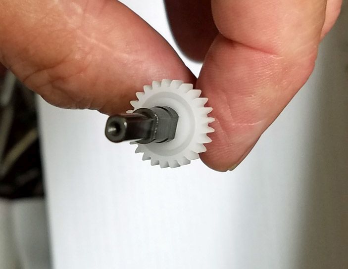
This is an Ozark wheel support with a very strong spring (from my little caboose project.) When it hits a bump, both wheels go up as the springs are too stiff.


