Just oiling the links and such during a routine water stop was difficult.
David,
Even more difficult in a 1/8th scale steam engine :). Many in the ride-on hobby have changed this valve gear on ten wheelers from Stephenson to Baker gear. In Baker valve gear, everything is done with linkage and links. No cams involved.
I have a few more photos of my old engine (I sold this engine back in January 2017 to a corporate executive pilot). He says he will have it under steam in about three months. These photos make it a little clearer on what actually “moves” to make the engine run in forward or reverse.
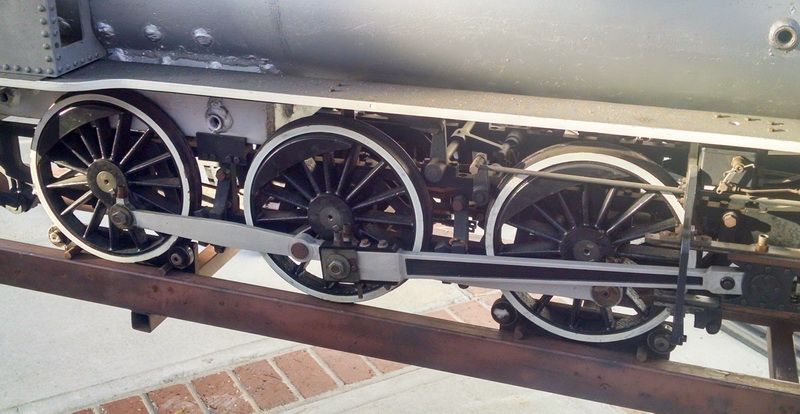
This view shows the three drivers on the engineer side of my steamer. Note the main rod and crank. This is the center of all the Stephenson valve gear. The eccentric cams are attached to this axle. If you look between the main center driver and the front driver, you can see where the rod for the reverse quadrant is attached. When you throw the quadrant handle forward in the cab, it moves the lifting link and this moves the eccentric links (the crescent shaped links with the precise slot where the die blocks are located) up and down.
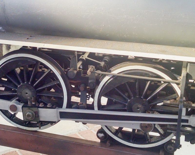
This photo shows a little more detail of the reverse rod link and the lifting link inside the frame. The small link between the reverse link and the front driver is the link that moves the valve stem and slide valve (in this engine) or a piston valve in the steam chest above the cylinder block.
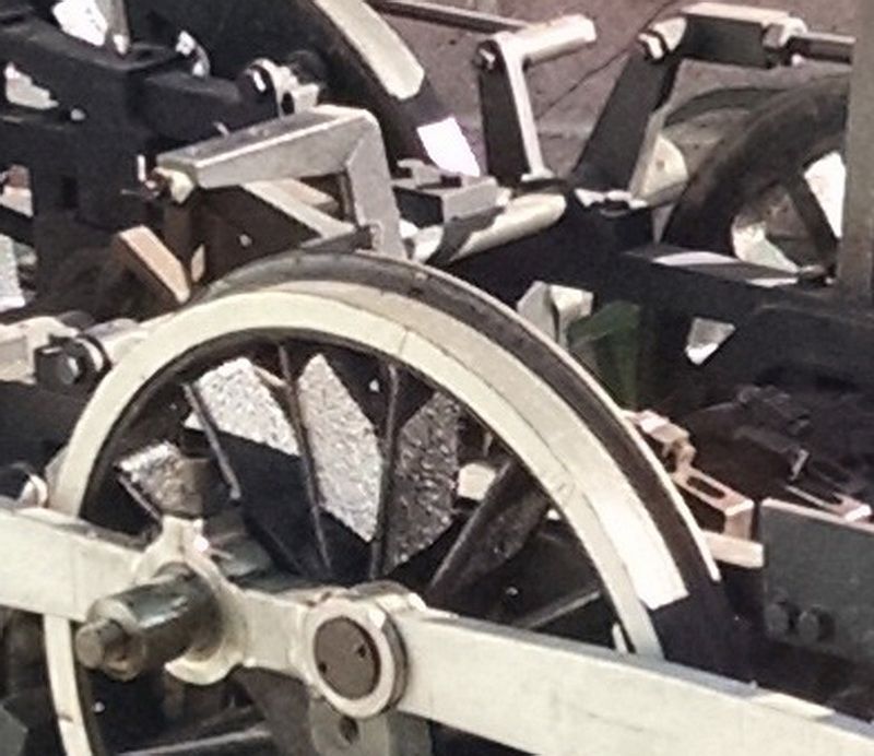
I hope thjis shows a little more detail of the reverse link, lifting link and the eccentric links in the background inside the frame between the drivers. The main rod has been removed.
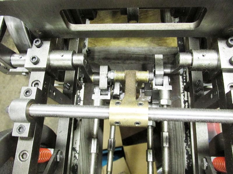
A much better photo of the valve gear components between the drivers and all inside the frame. Pretty complicated mechanism in its. State of the art for steam engines from the 1830’s right up to the early 1900’s. Just very difficult to maintain.
If you visit the Baltimore & Ohio RR Museum in Baltimore, you can climb all over Old #1, a 4-6-0, and move the reversing lever. You can then go around the side and have someone else move it so you can see what it does.
Gary,
That really helped me understand it
Devon Sinsley said:
Gary,
That really helped me understand it
Now if someone can explain to “me” how Utility’s drivers were not quartered I would understand better myself
" Rooster " said:
Devon Sinsley said:
Gary,
That really helped me understand it
Now if someone can explain to “me” how Utility’s drivers were not quartered I would understand better myself
That is a somewhat obscure question. Who’s ‘Utility’ - do I have to go back 4 pages to figure it out? Why were the drivers not quartered? And why is “me” in quotes?

" Rooster " said:
Now if someone can explain to “me” how Utility’s drivers were not quartered I would understand better myself
I believe they were quartered from left side to right side. Actually, quartering refers to the wheel pin position, for the drive rods, on one side of the locomotive relative to the other side.
Due to the way the front drivers and the rear driver, on each side, are linked together, they too are “timed” and will always rotate in the same positions relative to each other.
I think(https://www.largescalecentral.com/externals/tinymce/plugins/emoticons/img/smiley-undecided.gif)
Adam
I actually new that one. But didnt know what you were asking because I didn’t know the locomotive.