Jon Radder said:
So, I guess I’m going to end up paying some stupid tax.
What kinda tax?
Jon Radder said:
So, I guess I’m going to end up paying some stupid tax.
What kinda tax?
Rooster said:
Jon Radder said:
So, I guess I’m going to end up paying some stupid tax.
What kinda tax?
When I do something stupid that costs me money, I call the cost “Stupid Tax”. I’ve paid a lot of it in my lifetime (https://www.largescalecentral.com/externals/tinymce/plugins/emoticons/img/smiley-money-mouth.gif)
Finally got some mojo working to make some progress on this project. The breadboard…
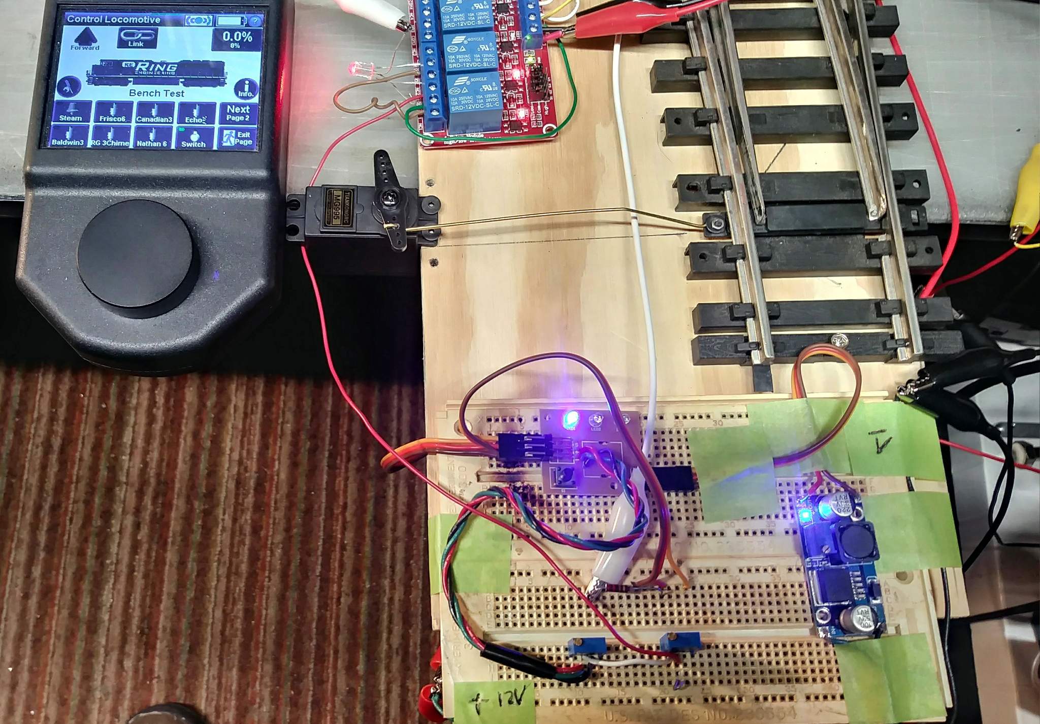
Over the last few evenings has evolved to this interface board…
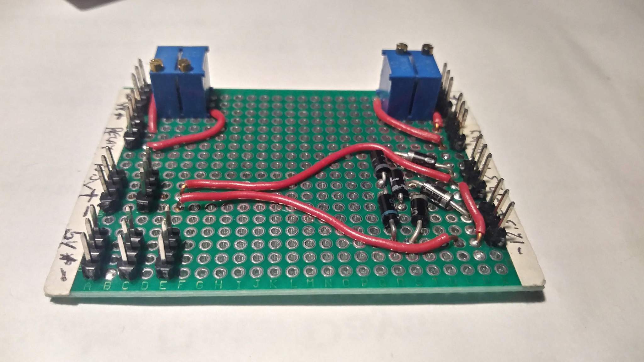
Mostly, this functions as a connection point for the various boards that make up the system. Active components are trimmer pots to set the rest and active positions of two servo tester boards and a diode matrix to drop the 13.5 source voltage to around 12.3V for the relay board. This board interfaces to a RailPro AM-1S, two modified servo tester boards, a DC buck converter to provide 5V for the servo testers and a relay board driven by the AM-1S to select the route and change LED indicators.
Once everything is in place I’ll post some detail on operation and some neat additions I made to the accessory project logic for the AM-1S.
Jon,I have no idea what you just said but the pictures are cool(https://www.largescalecentral.com/externals/tinymce/plugins/emoticons/img/smiley-laughing.gif)(https://www.largescalecentral.com/externals/tinymce/plugins/emoticons/img/smiley-foot-in-mouth.gif)
Rick Marty said:
Jon,I have no idea what you just said
Sometimes I don’t either (https://www.largescalecentral.com/externals/tinymce/plugins/emoticons/img/smiley-surprised.gif)
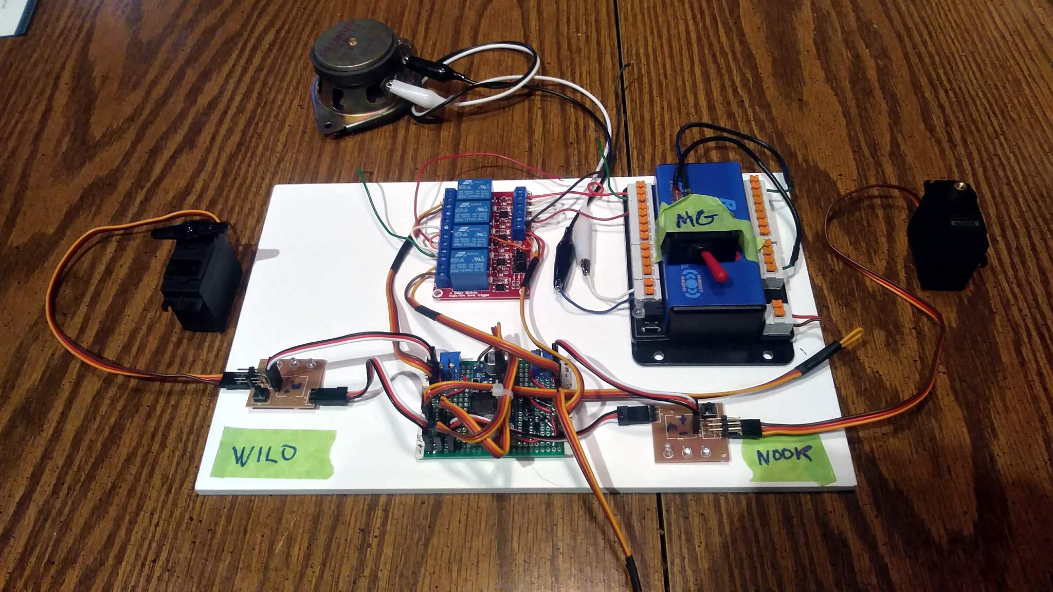
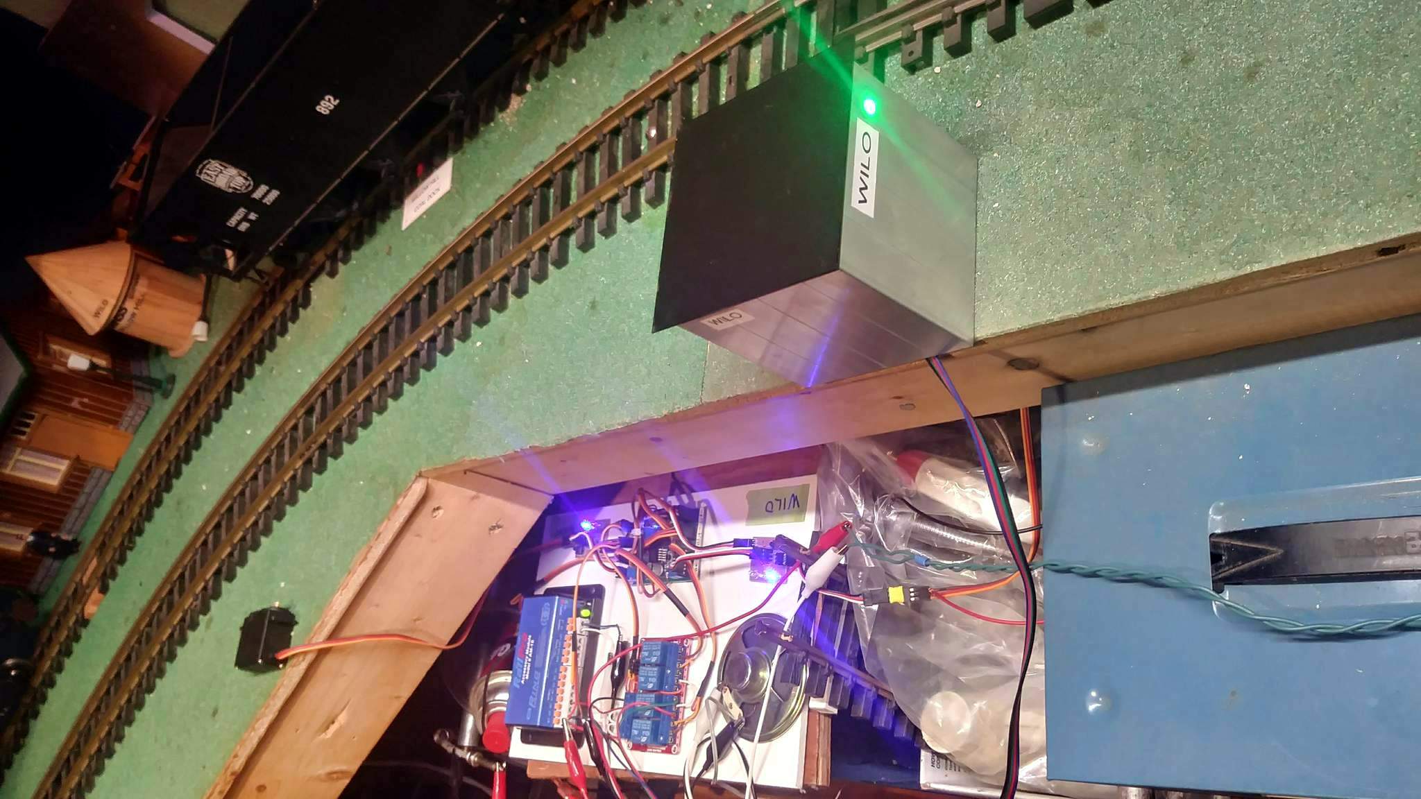
Did a full functional test with the actual WILO switch yesterday. Everything ran flawlessly after some minor tweaking of the trimmers. Ran trains through both routes from both directions multiple times and at speed with no issues. I have a boxcar that likes to pick that switch. Not sure which one it was, so I’ll need to test them all! The servo holds the points nice and tight against the stock rails.
I did have one issue. The logic for my bridge sense switch was reversed. With the bridge open to points were forced to the bridge route! Also the default condition was to take the spur, not the main. Don’t really know if this was a coding error or a wiring error on the interface board, but, since the breadboard test was good, I’ll go with a wiring reversal.
After pondering the issue for a while I decided to try changing the relay switch that adds the second trimmer from Normally Open to Normally closed. Perfect! Now the default route is the main and opening the bridge moves to points to the route away from the bridge.
The last step for WILO is to get the position LEDs wired up, install a speaker and get a roof on the equipment cabinet. Then it’s on to NOOK!
Soldered up a board for the position indicator LEDs today. Almost done!
Jon,
I hope this now allows you to edit your thread.
Thanks Joe - It does. Problem was it’s not “my” thread. It was started by GAP.
Borrowing an idea Motorola had for its Quasar Color TV in the late 1960’s “Works in a Drawer”

One day at work I had time to kill and lots of scrap 19mm foamed PVC board, so I designed and built a drawer and carrier utilizing some used glides I had salvaged. I had no idea what actual space I had to work with at the layout when I built it. I sized it based on the glides! When I got it home I discovered locating it was going to be a challenge. Changes needed to be made in bench and shelf support as well as moving stuff that would no longer fit on the shelf.
The challenge was met this week and the drawer was slung under the bench work. I then proceeded to figure out how I was going to power things and extend wiring from the drawer to the switch location. After primary and secondary power was figured out and wired I decided on ribbon cable to extend the 9 conductors I needed at the servo location. Here are the latest progress photos.
Drawer face is black composite aluminum board which will match the fascia once it’s finished…
In the photo below, in the back is a Meanwell 12V supply that has an output adjustment which I tweaked to the max voltage of 13.6V. The RailPro AM-1 does not like anything under 13 volts.
In front of the supply is a convenience outlet and a power switch for the supply. At right, the power supply output goes into a terminal block for future use…
And finally, the control modules are still mounted on a thin piece of PVC board and just sit in the drawer…
The only thing temporary in the above shot is the speaker. I haven’t decided yet on what speaker I’ll use and where it will go. At the moment the only sound being used is a warning bell when the bridge is up and points are forced away from the bridge.
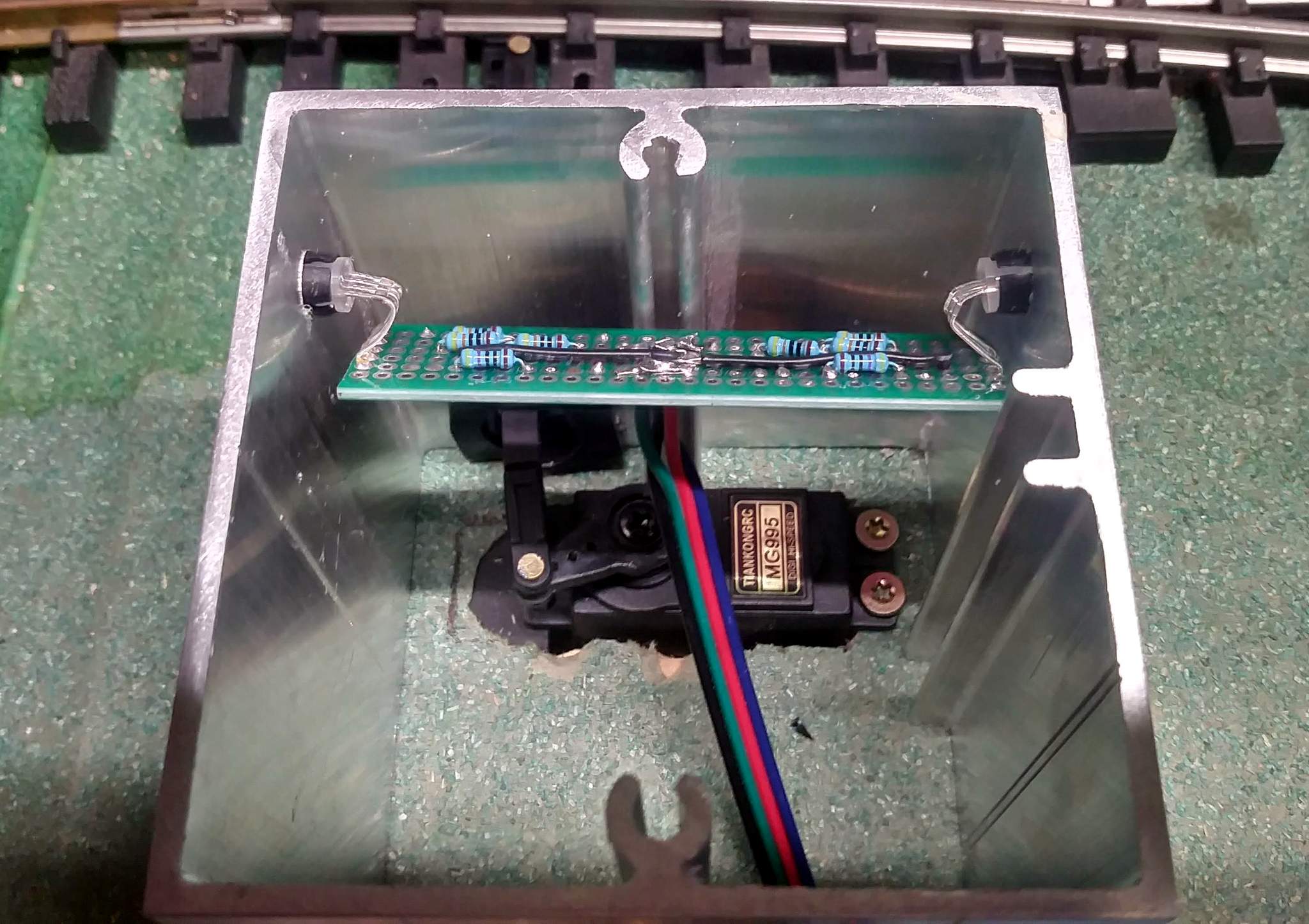
And finally, the ribbon cable terminates in a connector that will live in the equipment shed. The cabinet and LED board are not in this shot as it is being repaired…
All that is left to do now is re-make the LED board shown above. I damaged it beyond easy repair trying to fix a broken wire. When that’s done I’ll move on to mount and wire the servo and LEDs at NOOK.
Dan, do you know if the continuous rotation mode Sparkfun servo trigger board can be used in place of the Standard mode board?
I have only used the standard one but I would think it would. BTW: there is now another option. I picked up a few of these for a grade crossing signal project. https://www.vasileelettronica.com/pagina-prodotto/controllo-per-servocomando?lang=en
Thanks Dan, the last ones I ordered turned out to be continuous and Robbie’s are marked “standard”.
I’m really not sure where my head was at when I dismissed the Sparkfun controller as usable. The way my system ended up working, this board would work fine. I may pick up a few to play with since my system has a glitch that I can’t track down: servos wiggle randomly. Might be due to some RF interference or the like. Originally I thought it was a intermittent connection, but none found. Replacing my home-brew boards might eliminate it.
I’m currently using the AirWire Converter and Phoenix Coupler Driver to activate the couplers on my boxcars and have experienced the same issue with erratic servo action. Changing the servo in the KaDee remote coupler has been my only solution.
I’m now in the process of converting to the Railpro system, which prompted my initial question.


