Now we’re going to drill the ends of the air reservoirs. Start by removing the pipe stubs sticking out of the ends. You should be able to just snap them off.


Now drill 3/32" holes in the reservoir ends. Remember to start with small guide holes.

Now we’re going to drill the ends of the air reservoirs. Start by removing the pipe stubs sticking out of the ends. You should be able to just snap them off.
Now drill 3/32" holes in the reservoir ends. Remember to start with small guide holes.
tac Foley said:
Great idea, Sir, but I’m screwed from the word go. I have absolutely no idea of where you might obtain a piece of styrene anywhere near that big over here in UK.
tac
OVGRS
The aluminum should give enough strength to make your base out of multiple pieces of styrene. You should be able to secure the pieces to the aluminum, and then glue all the joints. As long as you sand the sides smooth, the skirts will hide the joints. You’d want to make sure there is no joint where the trucks get secured.
Shane
Now we’re going to do a bit of work on the trucks. First remove the center brake cylinders.

Remove the lip around the hole over the center wheel.

Now we’re going to drill a third hole between the wheels. Mark your center points and drill small guide holes.

Now drill the full size 7/64" holes.

Now remove your remaining brake cylinders. Notch the ends and drill 3/64" holes.

Now take a 7 1/4" piece of 3/64" brass rod. Make a mark 1/4" from each end. wrap the ends around a 3/16" drill bit using the 1/4" mark as the center of your curve. You want the end product to be 6 1/4" long.

Insert into the ends of your brake cylinders.
Now remount this assembly back onto the truck.

Nice photos and descriptions of how you are building this. Keep up the good work. You may have just remotivaited me to get back to finishing my GP30 project that stalled years ago.
Thanks for posting this project . Fun to watch it come together . It’s getting me motivated also to start another project .
Nice progress!
Thanks Guys. I look forward to seeing and learning from other people’s projects.
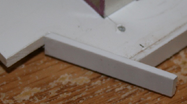
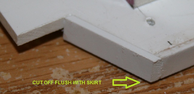
Okay, lets cut off the skirt ends flush with the step cuts.

Now take the piece you cut off, and glue it in along the step cut. Keep it flush with the top of the deck. Your angled cut from the previous step should fit in the inside corner.
Now cut off the protruding end flush with the deck skirt… Make sure you do all four corners.
Now cut four .06 x .125 x 1/4" pieces. These are going to complete the underside deck bracing to match your original SD45 base

Do both ends.
Now on your top side, you need to mark where the sections of the body will be placed. Start with a line 15/16" from the rear of your base plate. From that line, measure a 7" section, then a 7 7/8" section and lastly a 5 3/4" section. This should leave you with roughly 6" left to the front of your plate.
Tomorrow, I’ll post instructions for the upper framework. The circled numbers 1-4 will be used as a reference for some of this work.

Now we’ll need two .125 x .125 x 5" pieces, one .125 x .438 x 9 7/8" piece and one .125 x .438 x 15 3/8" piece.
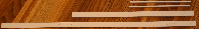
On the long .125 x .438 x 15 3/8" mark a line dividing the length into two sections 5 1/2" and 9 7/8". Remove 1/16" from the 5 1/2" section as shown below.

Referring to #1 in the previous post, glue a .125 x .125 x 5" piece flush to the outer edge of the skirt. The rear edge should start at your 15/16" base line shown in the previous post. This will leave it 1/16" from the corner of the skirt.


Referring to #2 in the previous post, glue a .125 x .438 x 9 7/8" piece in front of the above 5" piece, again flush with the outer edge of the skirt. The front of it should end up on the front line of the 7 7/8" section shown in the previous post.

Referring to #3 in the previous post, glue a .125 x .125 x 5" piece flush to the outer edge of the skirt just like you did on the opposite side.

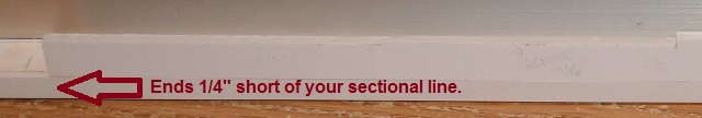
Referring to #4 in the previous post, glue a .125 x .438 x 15 3/8" piece in front of the above 5" piece, again flush with the outer edge of the skirt. The 5 1/2" portion that you trimmed 1/16" goes towards the front of the base. The 9 7/8" line should end up on the front line of the 7 7/8" section shown in the previous post, directly in line with the end of the 9 7/8" piece you mounted on the opposite side.
![]()
The end of this piece will end up 1/4" short of the front 5 3/4" sectional line as shown in the previous post’s drawing.
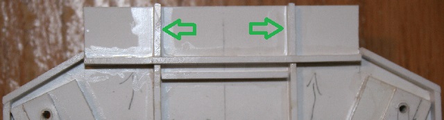
Now we’ll need one .125 x .125 x 1 1/4" piece (green) and two .125 x .125 x 1 5/8" pieces (red). Mark the center line of your green piece, 5/8" from each end.

Mount the 1 1/4" (green) piece 11/16" from your 15/16" base line and 1/8" from the end of the base. Match your center lines leaving 5/8" on each side.

Now mount your 1 5/8" (red) pieces on each side. I started by laying a straight edge and drawing a guide line between the green piece and the 5" side pieces that were mounted in the previous post. The line should be about 1/16" back from the skirt edge in the step cut. I layed the 1 5/8" pieces on top of the frame pieces that were already mounted, marked and cut the angles. Once mounted, you can see that they sit about 1/16" back from the step skirt edge.

Great step-by-step!
This just keeps getting better Shane. Maybe you or BD could put this in the ARTICLES section. A lot of this can be used to open the minds for other builds.(http://largescalecentral.com/externals/tinymce/plugins/emoticons/img/smiley-cool.gif)
Thanks Guys. I think making this thread is more time consuming then the model building, but I’m enjoying it. I’m trying to get a new video complete for my youtube channel as well, so I’m pretty swamped at the moment. If anyone is interested in the sights and sounds of real railroading, visit my youtube page.
I hope to add G scale videos eventually.
Shane
Okay take some 1/16" thick styrene and cut two 7 3/4" x 3 1/16" and two 7 7/8" x 3 1/16". On the 7 7/8" pieces, draw a line 1/16" in from each end as shown on the lower piece in the photo below.
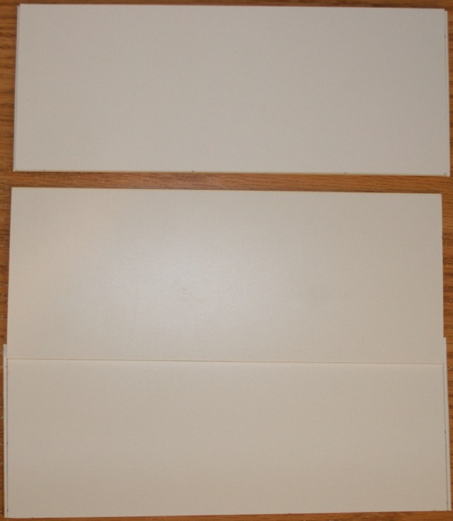
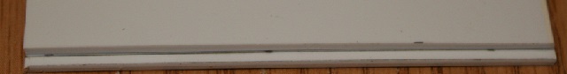
Now center the 7 3/4" piece on the 7 7/8" piece between the lines you drew. It helps if you set some weight on it. Glue them together.

Both ends will have a 1/16" gap.
Make two of these. The longer piece will be the bottom.

Now on the top face (shorter 7 3/4" section) we need to measure as shown below.

Mirror these measurements on the second piece. These are opposing sides of the center of the body.

Now we need to cut out a set of doors for each side using .01" styrene.
We’ll need:
Two 3/4" x 2 5/8"
Two 1 1/4" x 2 5/8"
Four 2 1/2" x 2 5/8"

Mark a center line on the 1 1/4" pieces. (5/8" x 2)

Draw dividing lines on the 2 1/2" piece into four 5/8" sections.

Now take a metal ruler, and cut along each line with a razor saw. Run the tip of the saw blade along the line 4 or 5 times until you have a nice defined line. I cleaned the tip of the blade after each cut. You don’t want to cut right through.

Now one at a time, place your doors on your marked up side pieces. I used some weight to keep them in place while gluing. Use your solvent sparingly as this thin styrene will distort easily if too much solvent is used. Too much weight could also cause distortion.


Don’t know if you know, but a member here (Burl Rice) has on Shapeway 3D prints of door latches and hinges. Build looks good so far.
I had forgotten about those until Craig mentioned it. Here’s what he’s talking about:
http://forums.mylargescale.com/15-model-making/61458-model-dabbling-now-into-future.html
