Large Scale Central

Delton Doozie Gearbox

I was replacing the drive train in a Delton Doozie as the original had a slipping worm. When I got it apart and took a wheel off, I found a little hex head screw holding the gearbox together. In this case it had loosened, so a quick tightening with a micro hex screwdriver and it seems right as rain!

Anyone need a spare Doozie gearbox?

After a frustrating morning drilling the new gearbox I am taking a break to post these few photos in case anyone is interested.

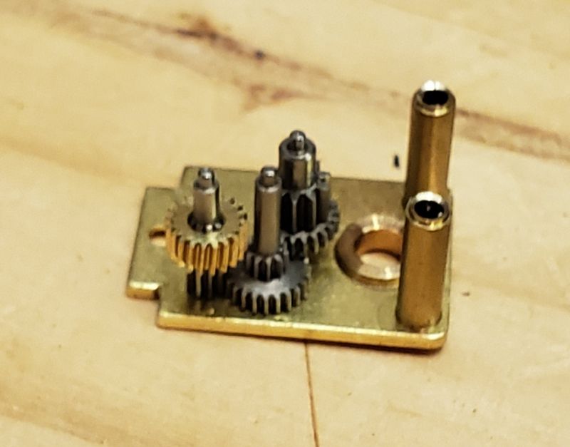
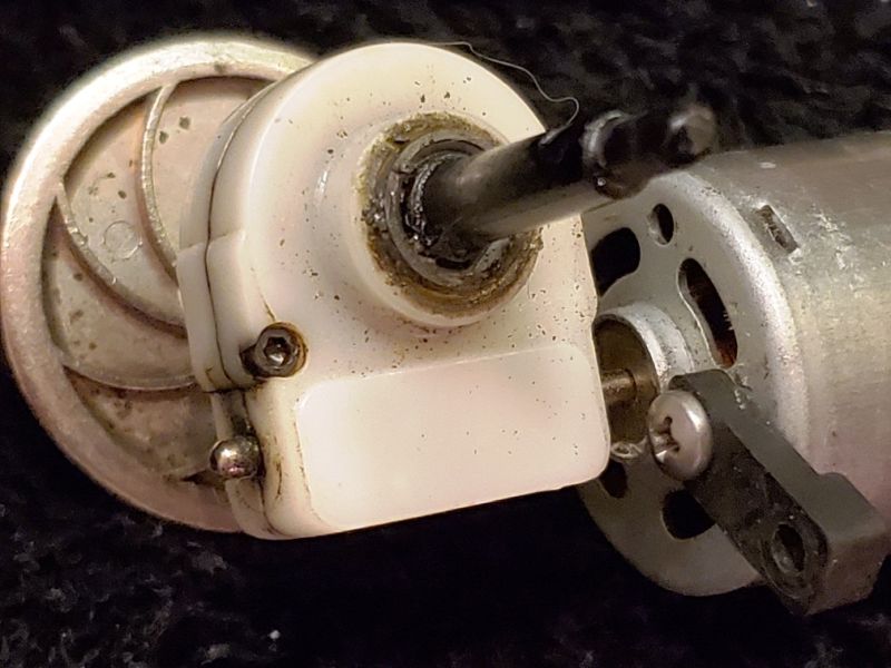
This is the new gearbox without gears loosely put together once I got both sides drilled 3mm. The brass case is sleeved with phosphor-bronze bearings, I think.

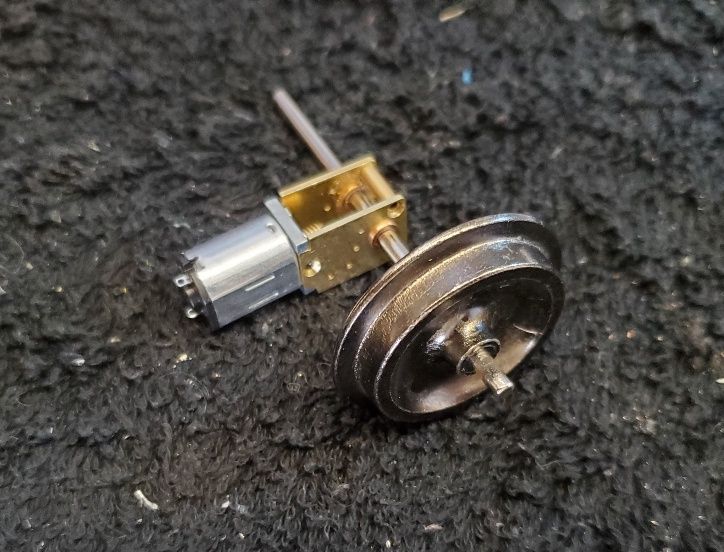
To back up a little, I started this project after noticing some micro-motors with right-angle drives on my favorite chinese website (aliexpress.) This motor, sitting on a small LGB can motor for size comparison, is rated 12V 120rpm and the shaft is spec’d at 3mm, the same as most of our axles.

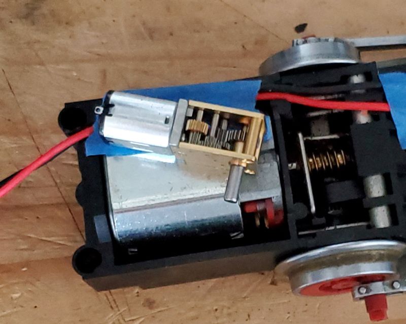
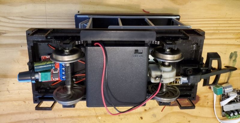
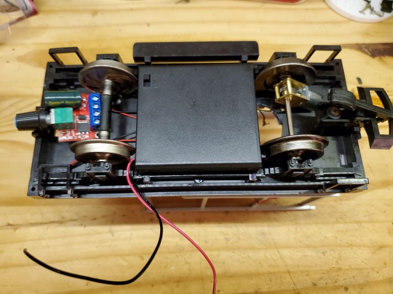
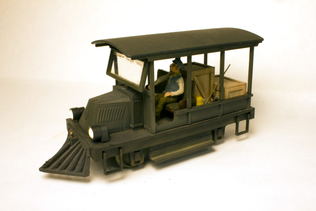
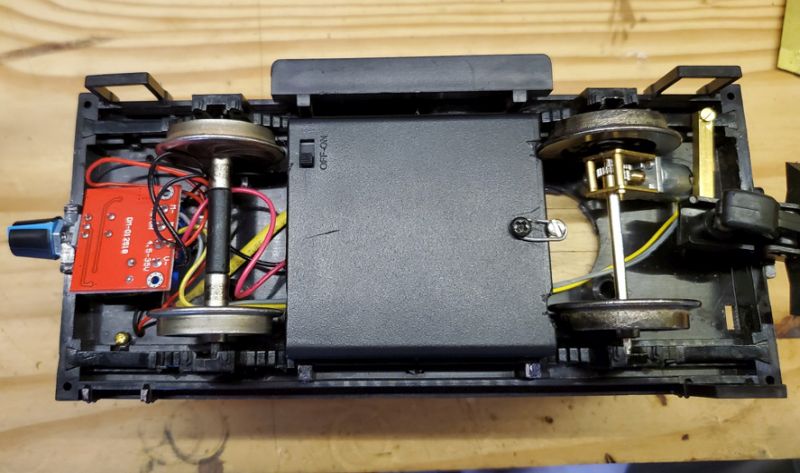
This is the general plan. The weight in the center of the Doozie gets replaced by a 6V “AA” battery pack, and a PWM speed control gets mounted somewhere. The gearbox goes - you can just see the micro-motor under it.

That was the theory. First I had to drill out the ends of the stand-offs/supports keeping the gearbox together at the axle, which means re-tapping them and screwing it together. Then I found that only one side was 3mm - the other was nearer 1.5mm so that had to be drilled. Here’s the geartrain without the final drive gear, which is also not 3mm - more like 2.3mm.

And without a proper workshop, drilling hard materials is tedious. Here’s the drilling rig under my Dremel which is on a drill stand so (in theory) it is vertical. That’s the side plate with the small hole which turned out to have a bearing in it. The knulred knob is a heat sink over a nail dropped into a hole, so if the drill grabs and tries to spin the brass side it doesn’t take the end off my finger. Next to it is the (steel?) final drive gear which has to be drilled out 3mm and fixed on the axle.

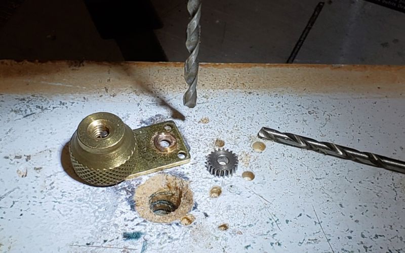
I ended up fencing the final drive gear in with some more small brads to stop it spinning, but haven’t yet got the 3mm hole completed as my 3mm drills aren’t hardened steel. Wonder if I have any more somewhere. . .

Now that the hard drilling is done, comes the handy tip, get some cutting oil for drilling harder or brittle metals.

For example; Not just threads works with drills and gravers too.

12 Oz. Thread Cutting Lubricant 92581 alternate photo #1

comes the handy tip, get some cutting oil

Thanks John. I have some in my Maryland workshop, but I am in Florida. . .

A little more progress. The Doozie is quite old and very fragile - every time I pick it up something breaks off. Guess the plastic is brittle.

I tested the motor on the bench with the 6V pack and the PWM speed control and it works. A bit of oil didn’t hurt.The motor with its pair of Bachmann wheels is back in the frame, and I managed to squeeze the battery box in by leaving off the top and snipping off a bit of the end at each side. A proper “axle-hung, nose-suspended” motor config which will need anchoring somewhere. I could put it in the hole where the motor used to be? But the truck now has a flat bed so I’d rather not.

Guess what? The Bachmann wheels are bigger than the Doozie wheels and are rubbing on the battery box. Something will have to be shaved.

I also tested the lights on the Doozie and nothing happened. I’m guessing, as they are just wired to gthe motor, that they are not LEDs so I may have to open them up and put some LEDs in the housings.

A little more progress in between Christmas activities.

I did replace the lights with LEDs and rewired them in series. They come on when you turn the battery pack on. Speaking of which, as there is room above the batteries, I decided to add the top to prevent the AA cells from falling out. I trimmed the sides with my mini-table-saw.

The wires are not exiting from the original spot, as that was right behind a wheel flange. I filed both ends of the box (you can’t see on this photo of the top,) to clear the wheels and re-routed the wires back inside by cutting a slot behind them, then I ran them out a new hole near the centerline.

The visible screw hole kept the top and bottom together. I used a longer screw and ran it through the floor by the driver’s feet (visible below.) At the back of the battery pack I drilled another hole in the centerline and used it to attached the pack to an upright screwed into the new rear deck. This photo shows the 2 bolts holding the wood to the frame, and the center screw is part of the battery pack mount. I guess a lunchbox or pile of rags will be needed to hide the scre heads - but once I put a coat of black paint on I suspect they will fade in to the background.

If you are wondering why I am using such odd screws, bolts, and other assorted bits - I am trying not to spend any money on the thing. I got it for virtually nothing, and once I finish making it run I will sell if for a bit more than nothing. So it is a question of raiding the parts and junk boxes. Unfortunately, my Florida home hasn’t been accumulating for enough years, so I do have to make things out of obscure junk.

The speed control is now mounted in the front pilot beam, and the wheels turn. The motor is 12V 120rpm, so on 6V it is turning less than 60rpm, or slower than one revolution of the wheels per second. Off to the Calusa Creek RR to give it a spin. . . .

Pete;

I do not wish to detract from your excellent modeling, but you really have me confused. The vehicle you show in your photos is something about the size of an old station wagon.

I have an original Delton Doozie, and it is in its original Delton box. It is a Mack railbus with the AC type hood and a combine type shorty carbody. It has four axles (in two trucks). The motor is in the rear truck, but this little railbus was notoriously slippery. I had to add two Wimmer lead figures to the seats over the rear truck, plus a pewter conductor to the rear platform to give the wee beastie enough traction to climb even a 2% grade.

Did Delton make another Doozie that I am unaware of?

Best, David Meashey

Did Delton make another Doozie that I am unaware of?

David - I’m afraid I am the instigator of the problem here. You are familiar, as I am now that you mention it, with the big Doozie:

I bought my ‘doozie’ from someone on FB who obviously did not know what he had, and I didn’t think of the bigger one. What I have is the Mack rail truck that ended up being sold by Hartland.

Known by Hartland as a “Woody”.

I will stop referring to it as a Doozie and it is now a “Woody”. Maybe I can persuade Bob to change the title.

Thanks for the correction (http://www.largescalecentral.com/externals/tinymce/plugins/emoticons/img/smiley-cool.gif)And please don’t be polite and call it modelling. I’m hacking a perfectly good (if old) rail truck to see how/if the micro-motor works!

Actually confusing was calling it a Delton in your 1st post too, when it is based on a Heartland Mack, which was never called a Doozie.

Thanks for clarifying.

Greg

And back to our regularly scheduled program . . .

A test at the Calusa Creek RR proved that the wheels were binding on the battery pack, so I re-designed the battery clamp at the back.

All wheels turn and it does move on my 2’ of test track. You may also note the piece of brass tube over the motor so it stays in place and doesn’t try to spin on the axle. The wires need tidying and some parts that broke off need remounting.

The back platform is now clear - the original ‘woody’ has a box covering the large motor - all I have are 3 screw heads.

I would have to say that the speed is walking pace at best, which isn’t very satisfactory. The motor is 12V and is only getting 6V which is part of it. I can’t adjust the gear ratio without throwing it all away, so I may just put the old motor back and sell it.

scales out to 4 scale miles per hour assuming your rail car is about 1:20 and your speed at 6v is about 60 rpm… (and your wheels are about 1.14" in diameter

In reality it is probably slower since speed of a motor is rarely linear with voltage.

Yep, pretty slow…

Greg

it is probably slower since speed of a motor

“Video at 10” or when I remember to dump it from my phone . . .

A Country Walker could still make money hauling 3rd class freight; as long as it gets there, good.

I have a book of railroad stories and often light is made of walkers passing the train/motor car/jalopy as if it was normal.

Walking pace just about describes it.