Large Scale Central

The "little short line" needed some power....

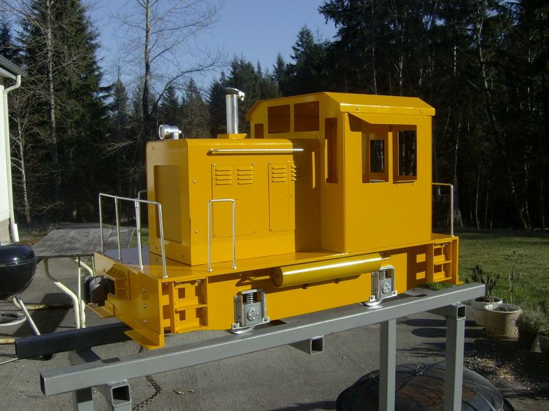
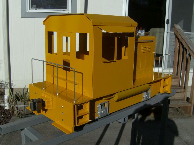
As you know, I have another thread going about the “little short line” I’m building to go around our home (for the grandkids, of course :)). Well the new railroad needed some added power to do some “switching chores”. This Super Husky (available from Eaton Custom Engineering in Castle Rock, WA.) fits the bill. Only weighs 150 pounds ready to run and is made of 6061 T6 aluminum plate. Has two small automotive batteries (Group 26) and is powered by a single 500 watt, 24 volt motor through chain drive to all four wheels. This engine can be lifted by two people and put in the back of a SUV with room to spare. Completely wireless controlled with Phoenix Sound exactly the same way we run our garden railroads. Pretty nice package and a strong puller. There is a video on the website that shows this single engine pulling 11, 1-1/2 scale gondolas. Very impressive for a loco this small.

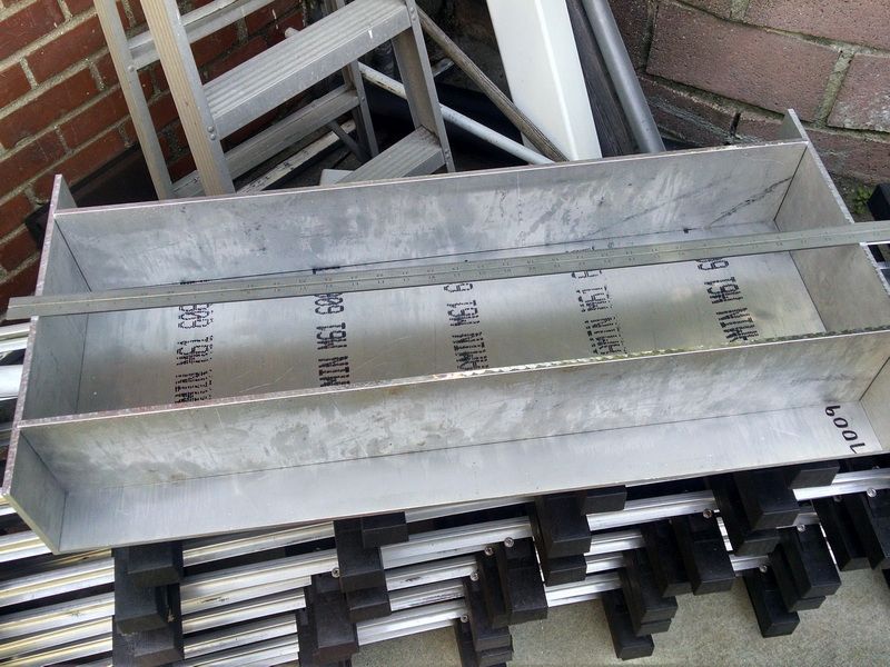
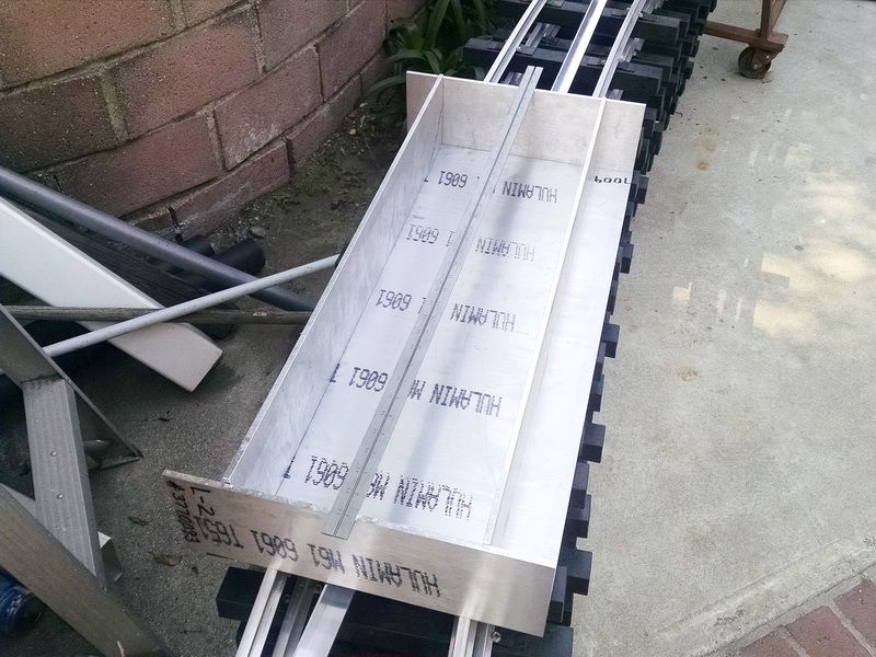
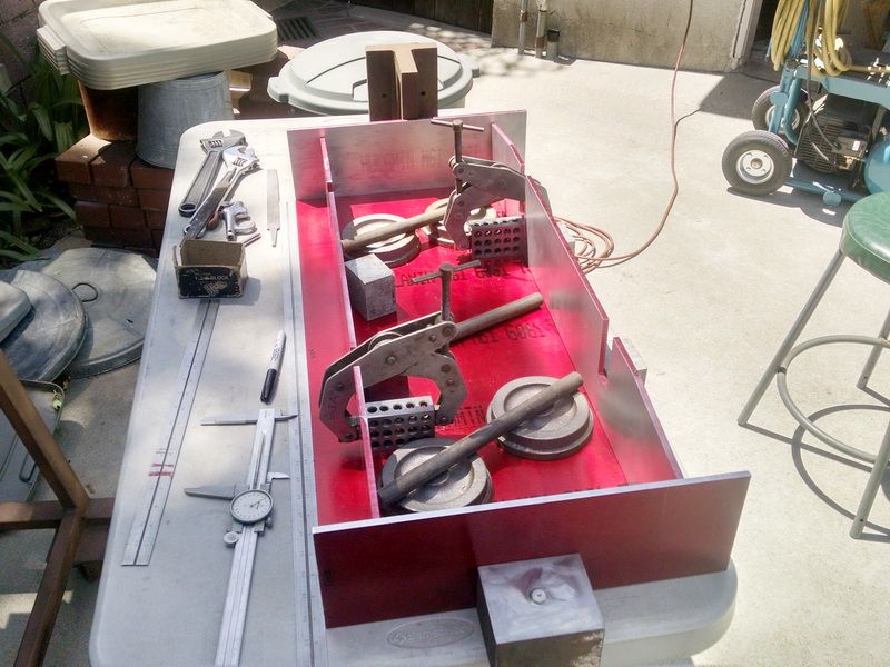
Today I picked up the aluminum material from a friend who got it for me, to begin the chassis build. I returned the pieces I needed to be sawed to my friend this afternoon at the Los Angeles Live Steamers facility. Once they are rough sawed, I can start to mill the pockets for the journals and fasten the pieces together with bolts and nuts and 1 X 1 X .125 thick aluminum angle stock.

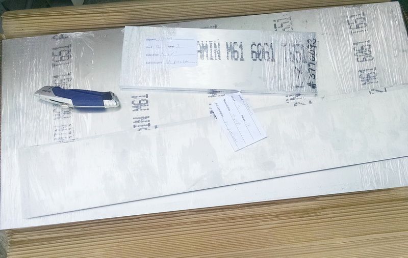
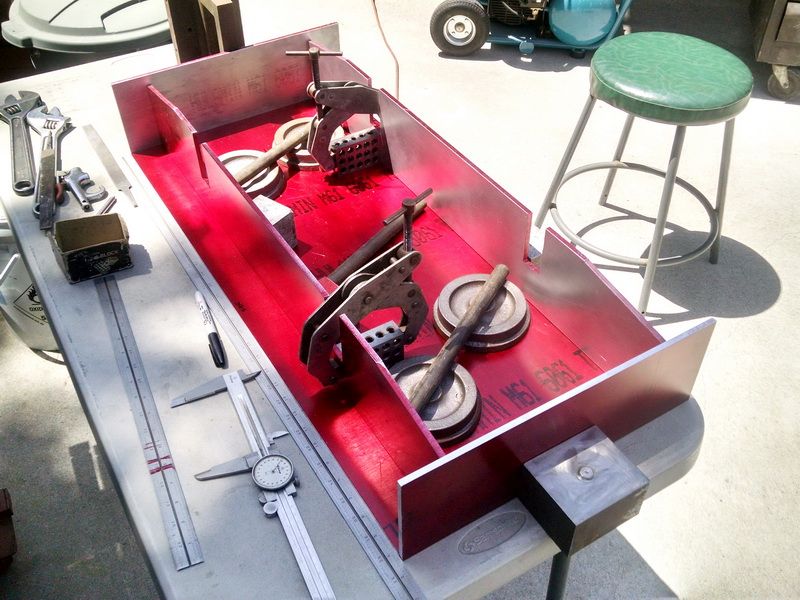
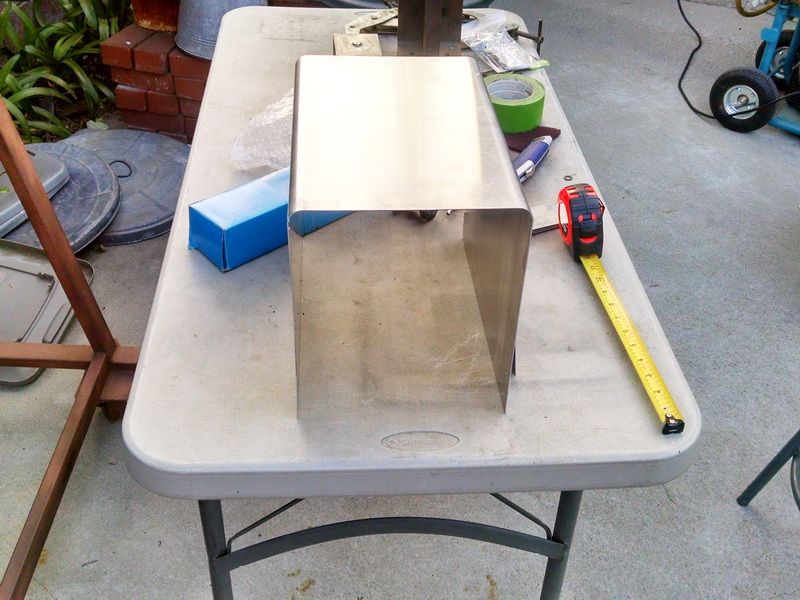
To get a comparison of size of this engine, that’s a 36 inch square head blade laying on top of the stock. 1/4 inch thick aluminum.

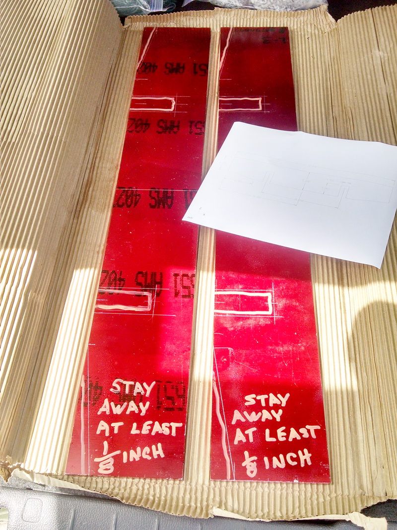
In the back of the car, ready to take to LALS and turn over to my friend to do the saw cutting.

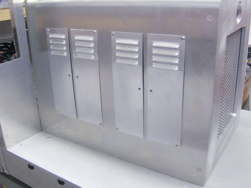
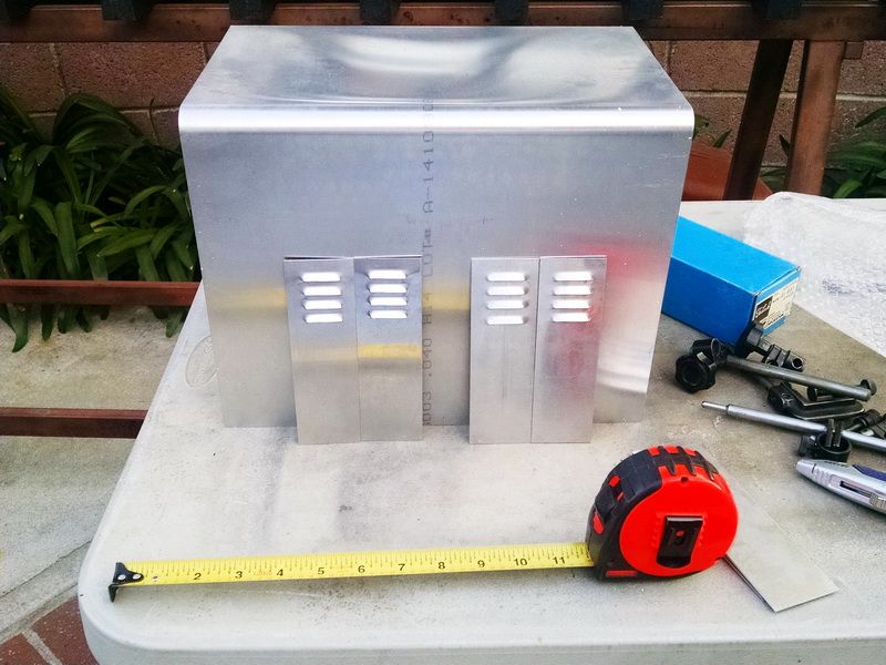
A couple of photos of the finished engine. When completed, it will look exactly like the old MDC model in “G” scale. Remember the Lil’ Hustler?

Very cool. (http://largescalecentral.com/externals/tinymce/plugins/emoticons/img/smiley-cool.gif)

Certainly cooler than my Athern with dual rubber band drive.

Wow that is cool. Would love to do that around my property.

What kind of suspensions do these big things have?

Forrest Scott Wood said:

What kind of suspensions do these big things have?

About a 3/4 inch diameter coil spring, with .090 wire, over each journal box.

Okay. I was wondering whether that was a detail or functional.

Forrest Scott Wood said:

Okay. I was wondering whether that was a detail or functional.

Forrest,

When you get to engines of this size, everything works. The springs actually have to function :slight_smile: (along with all the other mechanical items). The axles have 1.125 diameter ball bearings on each end and self-aligning flange ball bearing on the idler shaft under the chassis. All four wheels are chain driven.
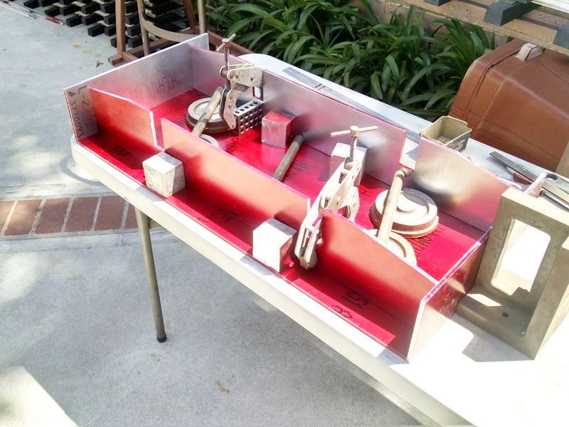
Gary Armitstead said:

Cute little bugger…(http://www.largescalecentral.com/externals/tinymce/plugins/emoticons/img/smiley-wink.gif)

Nice . . . . (http://www.largescalecentral.com/externals/tinymce/plugins/emoticons/img/smiley-smile.gif)

Really liking this build. I’m sitting here taking notes. Keep up the good work!

Gary,

That is really sweet! I have always loved that little engine in various scales through the years and it is just perfect for your “Grand children’s” railroad.(http://www.largescalecentral.com/externals/tinymce/plugins/emoticons/img/smiley-laughing.gif)

You didn’t really say but I assume you are building it from “kit form” ?

Thanks for sharing

Rick

Rick Marty said:

Gary,

That is really sweet! I have always loved that little engine in various scales through the years and it is just perfect for your “Grand children’s” railroad.(http://www.largescalecentral.com/externals/tinymce/plugins/emoticons/img/smiley-laughing.gif)

You didn’t really say but I assume you are building it from “kit form” ?

Thanks for sharing

Rick

Actually Rick, I’m “scratch-building” this engine :). I’m buying the materials (aluminum plate 1/4 inch thick). I had it sheared to finish size (plus/minus .005…cost a little more this way, but avoided the task of milling to size. When my buddy finishes the saw cutting, I will “pin” the two side plates together and set them up on the mill and machine the journal box areas. Found some 2X2 6061 T6 aluminum block in the shop and will make the journals from that stock. Cut the slots in the blocks so they will slide in the side plates and bore the 1.125 pockets for the roller bearings. Axles are already made. Turned those and the wheels on my lathe. I had some wheel castings laying around the shop.

I will have to order the chain sprockets and flange bearings for the idler shaft from McMaster-Carr. Everything is pretty much “off the shelf”. I have to get a quote from the local sheet metal shop for the aluminum for the cab. He will also do the bending and cut the doors and windows out. It’s a pretty simple engine to build actually. The single motor is a 500 watt, 24 volt motor.

Scratch built, even cooler!!!

Yea, the cab shapes look like a pretty straight forward fabrication: brake, slip rolls and nibbler.

I assume the axle bearings are press fit in the journal blocks??

Rick

Rick Marty said:

Scratch built, even cooler!!!

Yea, the cab shapes look like a pretty straight forward fabrication: brake, slip rolls and nibbler.

I assume the axle bearings are press fit in the journal blocks??

Rick

Yes the bearing pockets will be a couple of tenths smaller than the bearings. Makes a real easy press fit into the aluminum.

The funny thing about this build is that Rich Eaton (owner of Eaton Custom Engineering in Castle Rock, WA) builds these RTR or they can be purchased in “kit form” in “modules”. When I purchased my rail bender from him, that’s when I noticed this little engine. RTR they are about $3000, painted and delivered. You save about $500 when you purchase the kit. I inquired about a kit and he told me with my experience, he would just tell me what materials to buy, the sprockets I needed (pitch, diameter, etc.) and he even sent me a couple of cad drawings :)! So he is actually helping me to build this thing with tips and suggestions and a couple of drawings. I’m getting this engine for less than a 1/3 of the cost bhy doing the work and designing myself. Pretty nice guy to deal with. He’s also an Air Force veteran :slight_smile: and flies helicopters.

Also this engine is wireless controlled and has Phoenix Sound. I don’t even have to ride this engine to run it. I can sit on a bench at the club and “watch it go around the club track”. The range is about 200 feet! He has a couple of Youtube videos showing it doing that! Very impressive little engine!

In my other post on building a turnout, the switch stand shown is one he GAVE me. The guy is pretty cool!

Pretty nice guy to deal with. He’s also an Air Force veteran :slight_smile: and flies helicopters.

Also this engine is wireless controlled and has Phoenix Sound. I don’t even have to ride this engine to run it. I can sit on a bench at the club and “watch it go around the club track”. The range is about 200 feet! He has a couple of Youtube videos showing it doing that! Very impressive little engine!

In my other post on building a turnout, the switch stand shown is one he GAVE me. The guy is pretty cool!

Well being an Air Force Vet he has no other option but to be “pretty cool”(http://www.largescalecentral.com/externals/tinymce/plugins/emoticons/img/smiley-laughing.gif)(http://www.largescalecentral.com/externals/tinymce/plugins/emoticons/img/smiley-tongue-out.gif)

What is also cool is the Phoenix sound and didn’t you say it was Airwire control? Just like running our 1:20 stuff except you can wander over and go for a ride.(http://www.largescalecentral.com/externals/tinymce/plugins/emoticons/img/smiley-laughing.gif)

The Grand Kids will love this. Do they know your building it for them?

Well it’s been a month since my last update on my Super Huskie build, so this is this the latest…

I got back the 1/4 inch aluminum chassis stock back from the saw company that removed the material from the chassis side plates. Saves machining time when you do this and you get pieces that can be used in other places on the build. These photos were taken a few weeks ago…just didn’t have time to post them.

This photo shows the chassis clamped together to check the fit and “squareness” of the frame. The person that procured my material had these pieces sheared to a close tolerance (within .001-.002 of an inch, length, width and height) and absolutely square. This really saves machine setup time and there is virtually NO milling to be done on these parts. Even the bedplate (the large 15 inch X 32 inch piece on the bottom in this photo) was sheared .020 shorter so that it just drops into place between the two end plates. Leaves a small .010 gap on each end…paint takes care of the gap! You can see that the pockets for the journal boxes have been rough sawed as are the angles on the frame at the end plates. I was taking inventory of the material for the 3/4 inch diameter axles (2) and the 3/4 inch diameter idler shaft to transfer power to the four cast iron wheels. Also shown is the aluminum material (6061 T6) rough blocks to mill and turn the pockets for the 1.125 diameter ball bearings at each wheel. The cast iron castings for the wheels had already had in the shop. These will be turned on my lathe and will be 4 inches in diameter at the tread with an additional 3/16 high flange. They will be 3/4 inch thick and the axles will be pressed on with a 5-ton hydraulic press and .0001-.0002 interference fit.

Now I am drilling dowel pin holes on my mill so that each side will be pinned together and machined together at one time. This way everything will line up “dead on”. The pin holes will be in the same places as the bolt holes that will eventually tie the entire frame together with 1 inch by 1 inch 5051 T6 aluminum angle stock. Makes a light weight but very strong assembly. The entire finished engine will weigh around 150 pounds including the two Group 26 12 volt deep cycle rechargeable batteries. Pretty stocky little engine.

A couple of more shots…for size comparison, the two blades shown on the table are 18 inches and 36 inches long. 12 inch dial calipers and 12 inch Crescent wrenches.

One of the chassis sides on my mill. Trying to figure out the setup on my small mill table. Since this photo, both sides have been drill, pinned and milled. I’ll post photos another day.

I just received an email today, that my completed aluminum hood and louvered access panel doors were shipped today. Anxious to see what this looks like on my frame this weekend. BTW, the louvers are real…punched just like the prototype. The doors are each 2 inches wide by 6 inches tall. Made of .050 thick 6061 T6 aircraft aluminum sheet.

That’s all for now. I have a lot more work to do on this. Like Devon and his “Deadline” of July 31st, this loco has to be finished by Christmas for the grandkids!

Great Looking Engine

Dennis

Received the aircraft aluminum hood for my Super Huskie this afternoon along with the eight louvered access doors to put on the sides of the hood.

Looking great Gary. Wish I had the property and the budget to do this scale.

Daktah John said:

Looking great Gary. Wish I had the property and the budget to do this scale.

Thank you John. Property is ONE thing…but I’m figuring that I will have about $800-$900 into this build (including the Phoenix Sound and the wireless controller) by the time it’s finished. I am doing all my own milling and turning. I have a small machine shop and wood shop in my garage. This engine IS available from Eaton Custom Engineering in Castle Rock, WA for about $3100 RTR or about $2600 in “kit form”. Not too shabby since that is LESS than an Accucraft brass model.

We live on a modest suburban lot (11,000 sq. ft.) here in Burbank. AND I am putting in about 180 feet of 7-1/2 inch gauge track. See my other thread on “Building a shortline”. I will have less than $1500 invested in that including a 12 foot long #6 RH turnout. You need to be able to do a lot of the work yourself…that is the secret :).