Thanks folks, I am learning a lot. I just need to confess that, as a mechanical engineer, I have never trusted working on things I can’t see, so I don’t experiment much with projects that are reported to have electrons bouncing around inside. My EE prof always got a chuckle out of watching us ME’s trying to chase those little electronical things.
Back to the topic at hand:
Yes, Jon, the Meanwell has a trim pot that I carefully left alone (see above), so I decided to see what it does and sure enough, it adjusts the output from 27.8VDC down to 22VDC, no load.
David, the regulators you pointed out look affordable enough for messing around so the pair of Amazons are on the way.
Bob, it is tempting to go naked but for the pittance David mentioned, I think protection makes sense.
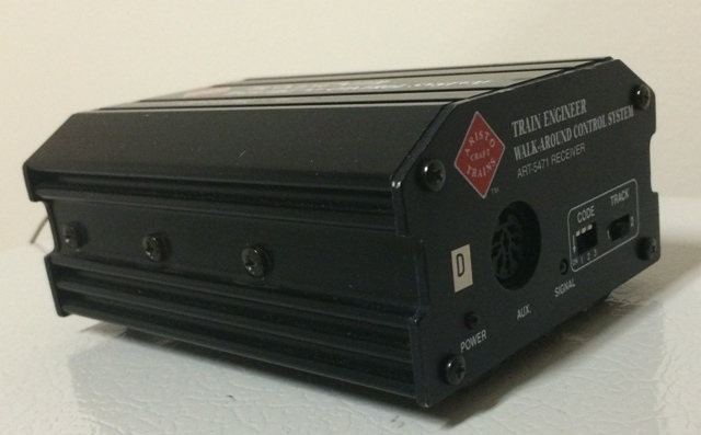
Todd – okay, you aked for it, now you get to watch my incredible video of the first test of the MW – diode pile – olde TE setup so you can see how olde it is:
Dan, as show in the amazing video above, I do have a fan in the Meanwell housing and I will have two fans in the enclosure for the 2 TE’s. I hope that handles the heat.
Thanks to all for your responses!