Large Scale Central

V&T Derrick 50

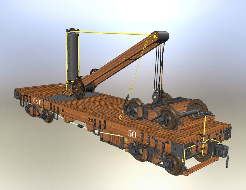
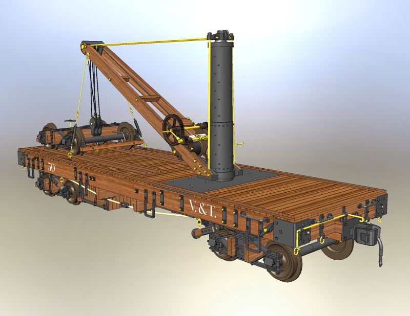
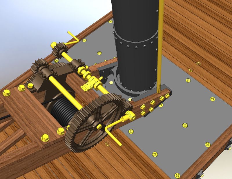
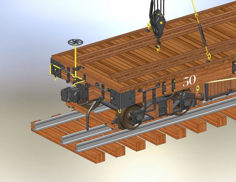
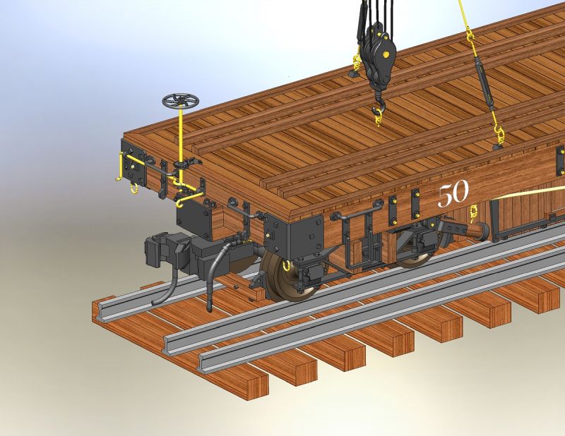
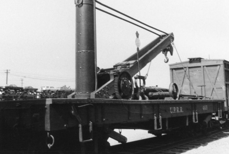
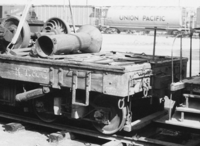
Off and on, over a few years, I’ve been researching and computer-modeling a derrick car that the V&T used in the late 1800’s. It’s a long story, and I’m not sure where to start, so I’ll just dive in. Here’s a couple images of the design model.

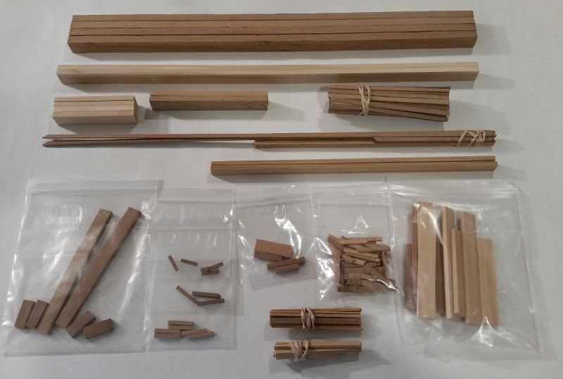
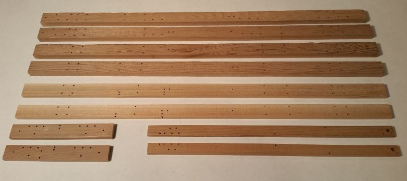
There’s gobs of hardware on this thing, so lots of 3d printed parts. Lots of individual boards, lots of holes to drill. I’ll post on all those in weeks ahead.

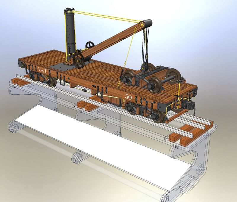
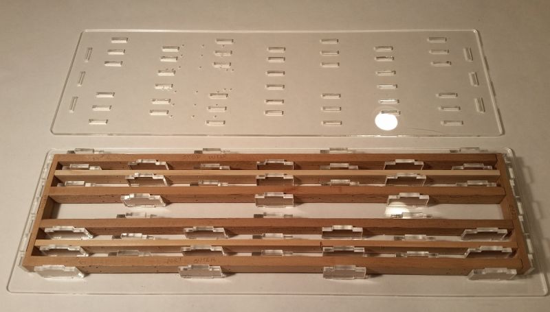
I finally began construction on the project last weekend, on the display. Yeah, I know that sounds weird. But since I’ll be presenting on the car & model at the next V&T conference, I needed a display base that can disassemble and pack flat in a suitcase. I learned the hard way how not to do that with the V&T flanger #51, where I dragged a big wooden display / mirror to show the flanger mechanism. This display also needs a mirror to show the underside, to show the complicated mast base. Here’s the design model,

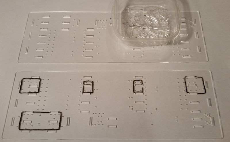
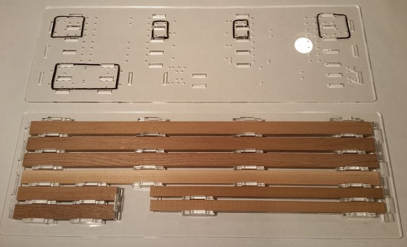
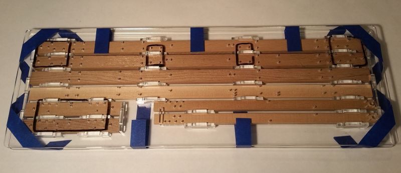
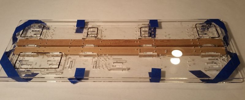
The parts for the display were cut on the laser from acrylic. The mirror is mirrored plex (which has a protective film on it, so doesn’t look great in this pic).

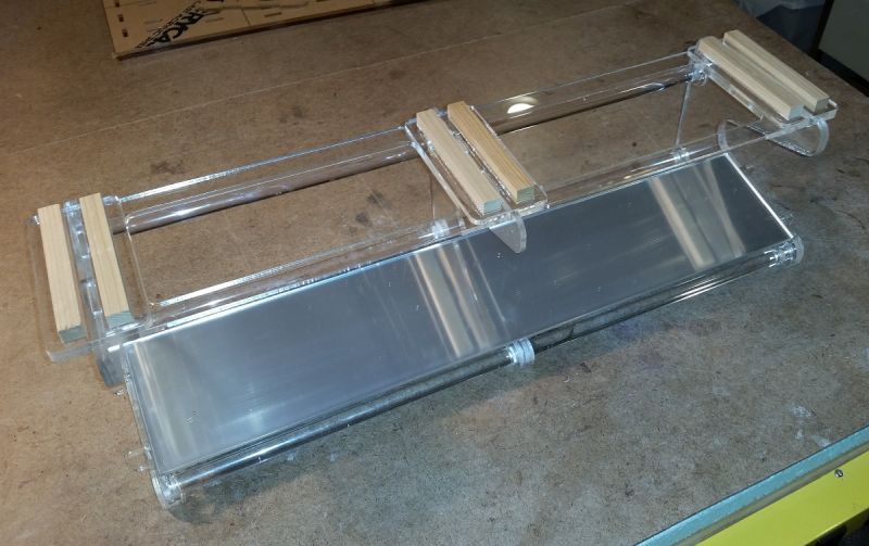
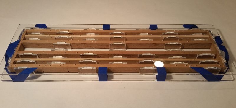
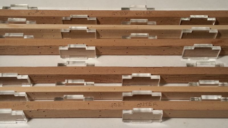
The parts interlock (without fasteners), and are quite rigid. Now that I’ve put it together though, I realize it doesn’t need those pricey 1/2" rods at all. If I do another, it won’t have those rods, only a couple more laser-cut joists that snap into slots. Another thing, the end pieces are glued/laminated; but it’s hard to do that cleanly, and there’s plenty of micro bubbles visible. I asked my artistically-dependable wife if I should spray the ribs flat black, she said no, no one will notice the bubbles if I don’t point them out. So I’ll go with this thing, and move on to the actual model.

'Mo later,

===>Cliffy

That’s really nice!

Gauge & Scale.

The trucks were a kinda big deal on this project. After looking at a number of commercial options, including beauts from Iron Creek Shops, I decided to roll my own, using 3D printed parts and wood. I’ll go over their construction as I get to them, but for the present, I wanted to point out the gauge and scale problems with this build.

I wanted to model on an actual scale, on a model that wasn’t compressed. I’m using 1:24 on my “formal” modeling projects; so for this model, that means it’s pretty long – because it isn’t compressed, like all the LGB stuff. That’s important, because I need the room to fit in the derrick without the compression rippling though the rest of the model.

The other problem is gauge. Since I’m doing 1:24 on 45mm gauge, that’s narrow gauge. But the V&T was standard gauge. So that means the trucks, if they’re to run on my layout, are too narrow for a prototypical model. The solution I found was to make two sets of trucks: one narrow gauge (for running), the other standard gauge (for display / discussion). Well, and one more standard-gauge truck for display, on the deck (as shown), because that’s how the ol’ #50 was configured in her best (and final) photos. So, five trucks for one car model.

The display will be dual-gauge, to support either truck configuration.

Going to be another good one to watch Cliffy!

Kewl! How long is this? What are the implications of non-compression?

How are the winches driven?

Cliff Jennings said: … without the compression rippling though the rest of the model.

Haven’t seen/heard that exact phrasing before but it definitely transmits the concept well; that is indeed what happens.

Thanks guys!

Chris, thanks brutha, I’ll do my best!

Jim, Forrest, measuring between coupler ends, it’s 20.29" long; length of the deck is 18".

About the compression I wanted to avoid, I originally started the project thinking I could use a commercial flat car, say, B’man or LGB, but those are quite shorter. (I’d measure, but I’m in a hotel at the moment… another work trip). Since the mast stabs through the deck, between a truck and the needle beams, there wasn’t room for the mast’s underside details. Another example is the Bachmann truck frames I was going to use, until more recently. Though supposedly 1:20-ish, their axles were about 1/2" too close together for this 1:24 model.

john, it’s a hand-operated winch, with a handle on either side (for 2 man op, if needed; or maybe also just for convenience). When the derrick was sold to Paramount for movie work in '47, PM mounted a tiny steam or air motor (powered from the loco) on the boom to drive it. It’s shown clearly in the movie Whispering Smith, which has the best (and apparently only) photography of the derrick in actual operation.

Here’s a detail shot of the model winch.

Yellow parts are brass, black is 3d printed; wood is cedar.

Thanks for viewing,

===>Cliffy

Truck Differences.

I mentioned there were 5 trucks in the project, with four different versions. The truck beneath the mast doesn’t have brakes, because there’s no room for the rigging down there. So, with and without brakes, standard and narrow gauge. The cosmetic one on the deck is an extra standard gauge, with brakes.

Here’s what the gauge difference looks like. The standard gauge configuration has more realistic body-mounted couplers. I can’t use them on my layout (curves are too tight), so these couplers are just for show; they plug into a drawbar socket.

The narrow gauge config has typical truck couplers, modeled along a Bachmann design. A blanking plate plugs into the drawbar socket.

===>Cliffy

Cool project, Cliff. I have coke and popcorn in hand waiting for the show to begin (https://www.largescalecentral.com/externals/tinymce/plugins/emoticons/img/smiley-wink.gif)

Cliff,

Not only a 2 man drive system but it looks like a 2 speed winch as well.

Correct me if I am wrong but it looks like the handle shaft is made to slide over; it is shown in the gear reduction mode in the picture, if you slide the handles over and lock them in you would be in direct drive to the drum gear. I suppose the change would be for the amount of weight you were trying to lift. For instance a truck would weigh in around 5-6 K, that would take some pretty serious hand cranking.

Rick Marty said:

Cliff,

Not only a 2 man drive system but it looks like a 2 speed winch as well.

Correct me if I am wrong but it looks like the handle shaft is made to slide over; it is shown in the gear reduction mode in the picture, if you slide the handles over and lock them in you would be in direct drive to the drum gear. I suppose the change would be for the amount of weight you were trying to lift. For instance a truck would weigh in around 5-6 K, that would take some pretty serious hand cranking.

Holed it in one, thanks Rick! Here’s a summary of some calcs I did a couple months ago. The thing needed to pick up an end of a typical box car (empty) and set it back on the rails. And in the Whispering Smith movie, that’s what it was in the act of doing. That was with the mini steam engine powering it, but before then (when in V&T service) two men could have done it.

BTW, I’m not sure what diameter of wire rope was used here, but I’ve been assuming 1/2" -ish. 10 tons would have been nearing the limit of even modern 1/2" rope, which has a min working force of 10.7-11.5 (depending on the winding). Then there are the limits of bearings, fasteners, cable clamps, etc. Point being, spreadsheets are one thing, reality and common sense is another. I doubt they’d have cranked it to 10 tons. But unfortunately, I haven’t found any manufacturer’s ratings. Though the identical mechanism is shown in Fig 77 of Car Builders Dictionary (1888), they don’t cite a capacity. If anyone comes across more info, I’d be grateful to have it.

Cliff

Those lifting weights at the hook are pretty impressive for a hand winch. Of course ever time you wrap a block you double your lifting/pull capacity.

Looks like a heck of a fun project and is historically meaningful. Keep us posted.

If this build even comes close to the most excellent computer model it will be a head turner. I cant believe the details you put into the computer model. I love all the fiddly stuff this car has on it.

Thanks very much Devon! Yeah, the car had a lot of gingerbread on it; I kept finding another piece of hardware to account for, it seemed endless! (https://www.largescalecentral.com/externals/tinymce/plugins/emoticons/img/smiley-laughing.gif)

Here’s a couple proto shots by my friend Mike Collins, who’s probably the leading expert on this car (and lots of other V&T subjects).

I got back to this project today, finishing up wood cutting, and getting into the pre-drilling.

Most of the cutting was done last weekend, but I needed some larger stock to do the four main sills. Jim Warren (formerly of Northwest Precision Lumber) cut the beams to spec, and I had them in a few days. Details of that discussion are here. Here’s the parts, including the ones for the underslung toolbox and the various trucks.

Then came drilling. This thing has gobs of holes, for the many truss rods and hardware bits (which have one or two gluing pins that go into the wood). So rather than mess with drawings and hand-measuring, I designed and lasered a drilling template for the main sills and the boom.

These holes are 1/16th and 1/32. All are through-holes, except the ones in black rectangles go only half-way.

I didn’t glue in the spacers, just set them in and taped things together.

The drilling went pretty quickly. Two of the main sills (center and intermediate) are identical, so needed to be re-run on the same setup.

The result of this was all the horizontal holes, two sizes, either thru or half depth.

Next came the vertical hole drilling, and I set this jig up to serve as an assembly jig as well.

The bottom side especially has a bunch of holes.

Here’s a closeup of the underside, in the boom mast area.

Next step will be notching several bits, and then getting into the frame assembly.

Cheers,

===>Cliffy

Wow! Now that is a lot of holes. Drilling jig looks like it made the hole drilling much easier and more accurate. Great work, Cliff.

Hi Dan, yep, the actual drilling went pretty quickly – maybe 40 minutes for each step (horizontal & vertical), including bit changing.

And I agree, I think / hope this will end up a lot more accurate than I could have done otherwise. When I’ve marked things out in the past, being as accurate as I can, it’s time consuming. And it’s subject to several tolerance areas – the main one being whether and where a (very flexible) 1/32 bit feels like walking when it hits the harder grain part. With the template, the bit doesn’t walk, yay!

(Side track: But maybe I should start chucking the bit to have a minimal exposure & less flex? But then, my Dremel vibrates, and that would open the hole up more… Not sure about that remedy.)

Much appreciated Dan,

Cliff

Cliff, I’ve made several drilling jigs for various projects, I just 3D print mine. I doubt my printer is capable of getting a very accurate 1/32 hole, though. One thing I’ve found with the plastic, however, is that after multiple uses, the jig holes tend to get wollered out and it loses its accuracy. Now, that issue may lie somewhere between the floor and the drill (https://www.largescalecentral.com/externals/tinymce/plugins/emoticons/img/smiley-wink.gif)I really enjoy watching your projects come together. You do fine work.

Right you are Dan, the holes egg out with any multiple use. And maybe it’s between the floor and drill (haHA!!), but maybe it’s mainly just the softness of the guiding material.

With these acrylic jigs, I’m experimenting to get a technique that would work for a run of multiple (ore) cars, and that would require multiple-use guide holes. That would require drill bushings, and in this size and frequency, a simple brass tube should suffice. If it was a really high run, I’d go with something industrial, maybe something like these.

Thanks again!