Large Scale Central

Beating the Boredom - Triassic Gilpin Ore Wagon "kit"

After completing 6 little Trail Creek 4-wheel cars (pictures later this week as I should be running them tomorrow,) I took down my next project, a bunch of Triassic Models Gilpin Ore wagons - yet another Peter Kaisan estate buy. The kit is quite interesting, so I’m posting the details for your entertainment.

A little background: Triassic is/was a UK laser-cutting kit company, and the owner, Alan, died in 2010. It was taken over by Mike (?) who is currently producing rolling stock for The Train Dept. The Gilpin Tramway is the only significant 2 ft gauge US railroad, and it was based in the gold mining area of Colorado near Victorville. The reason it was of interest to the UK guys is that they have a lot of 2’ gauge railways to model, and they use Gauge-O 32mm track at a scale of 1:19, (which is close to our 1:20.3 hence my interest in these ore wagons.) Mike indicates he can find no trace in his Triassic files of the Gilpin ore cars, but he does have the plans and files for the Gilpin caboose, which is a really cute 8-wheel car. (I told him I wanted one, but he’s pretty busy so it may be a while.) I found a photo online:

While poking around looking for a pic of the caboose, I also found a photo of the ore wagon that was made from the kit:

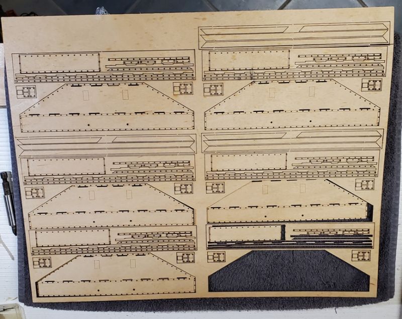
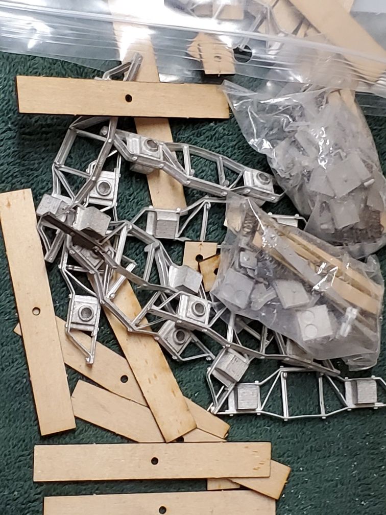
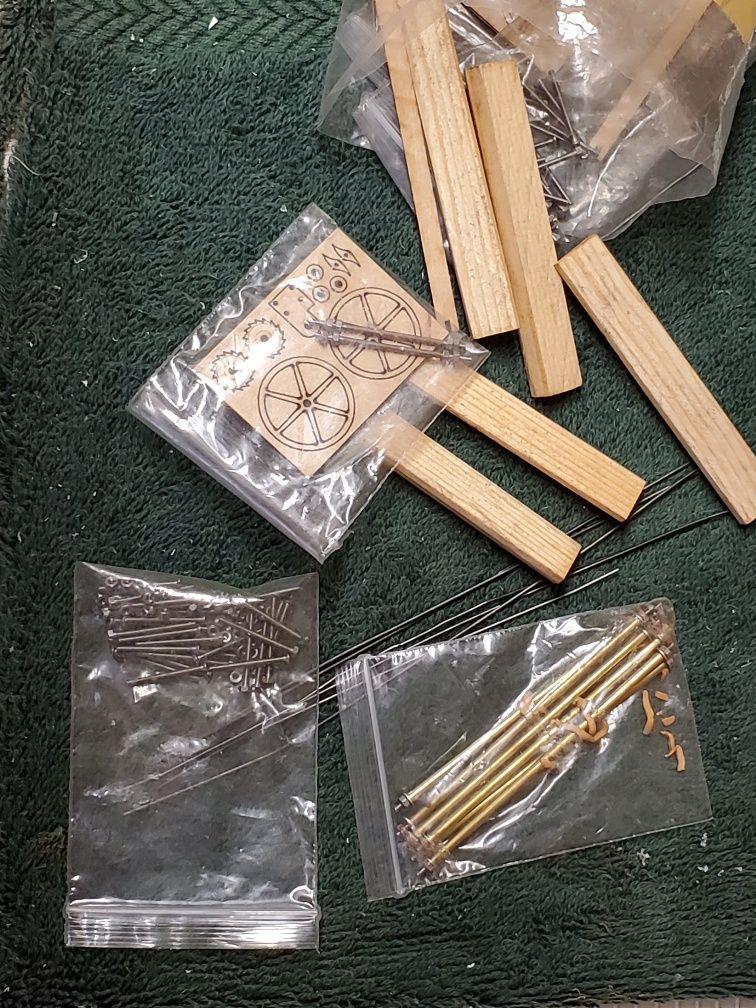
So, here’s what I got as a “kit”. There are 2 sheets of thick plywood (1/16th?) and a sheet of ‘trim’ that is thinner, and looks like it fits on the outside of the wagon.

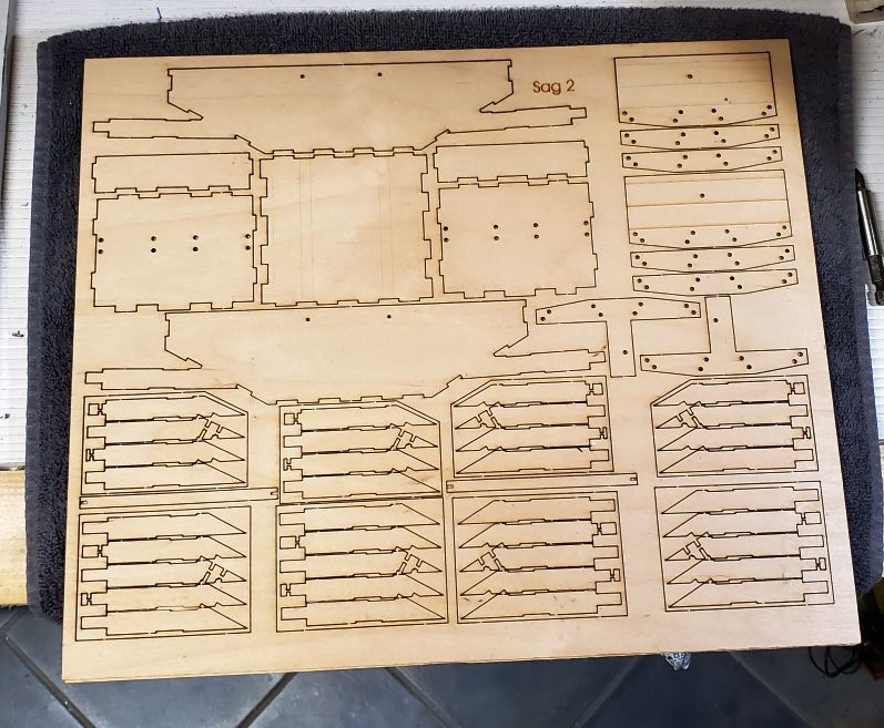
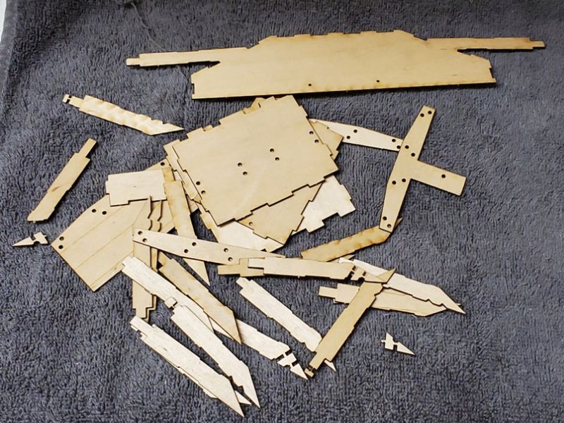
No instructions. And a plastic bag with lots and lots of bits of wood which presumably came from another of the thick sheets at some previous time. The thin ‘trim’ seemed to have enough for 3 wagons, so that’s what I assume I have.

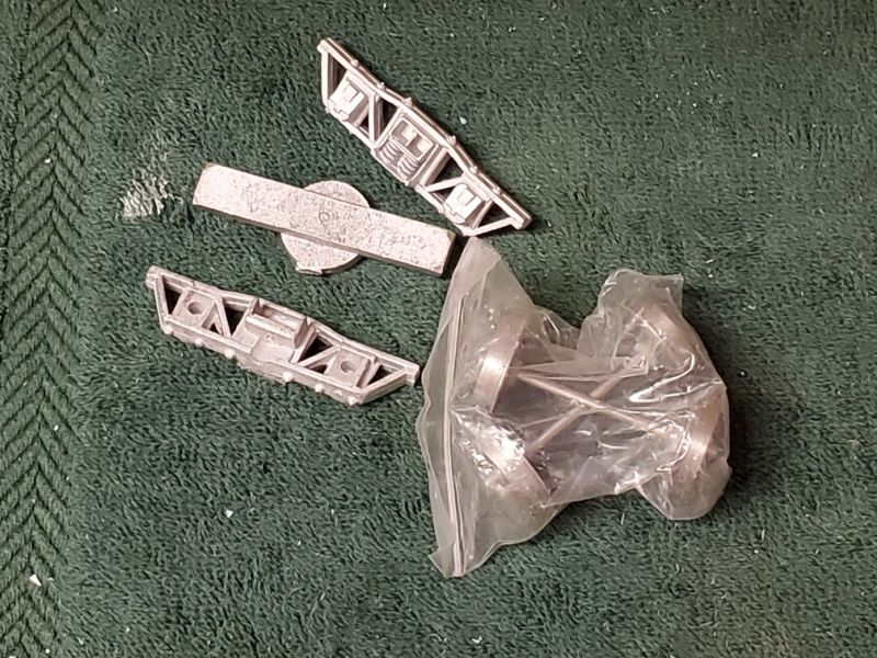
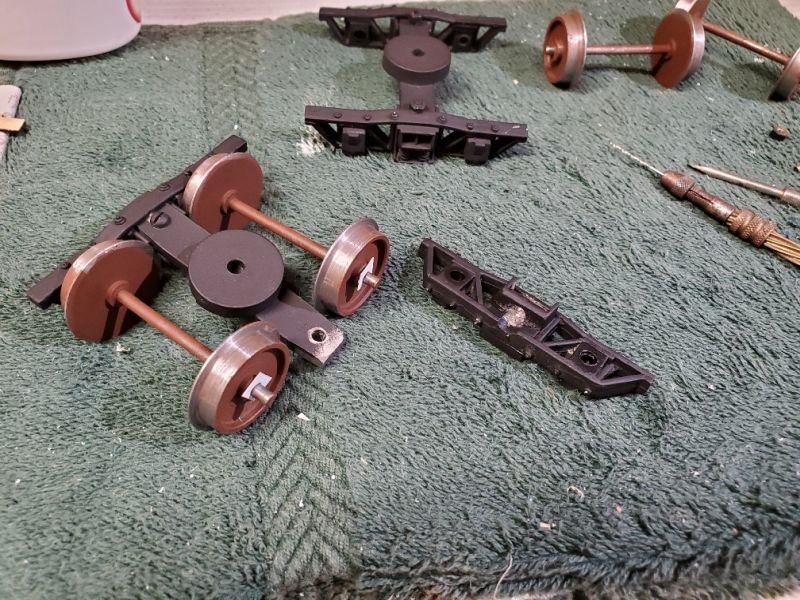
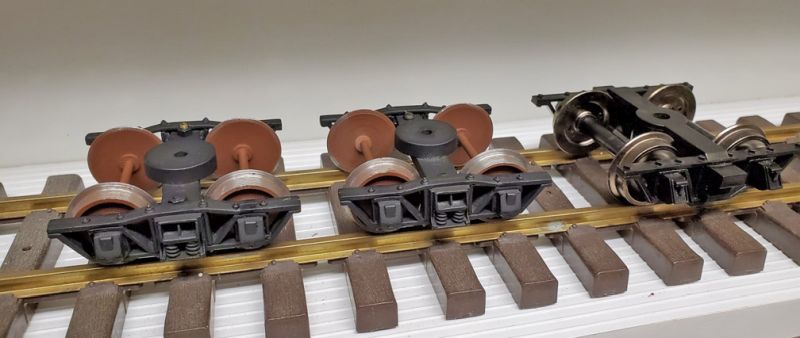
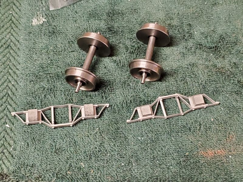
There are also 4 sets of trucks that consist of sideframes, a stretcher/bolster and a few bolts to hold it together, plus 4 sets of complicated parts for trucks, so I have 2 sets. There are 4 sets (8 wheels/4 axles) of 32mm gauge wheels and the same for 45mm gauge wheels. I’ll get back to the trucks and wheels later in this thread.

The pic is of half the parts, as I figured there had to be 2 ends of the wagon so I split them up. I could not figure out why there were so many pieces with an arrowhead end but different sizes of tabs on both ends.

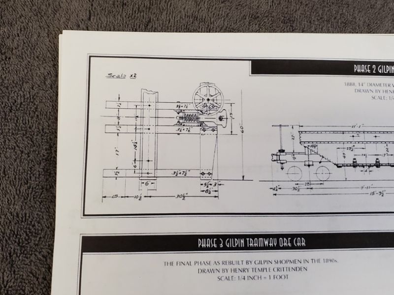
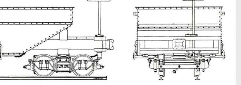
I have the NG&SL Gazette DVD on my computer and I found the articles about the ore wagons with drawings. This detail of the end beams looked promising. [However, the drawgear, with springs, is just like the Ozark stuff I left in Florida! Murphy’s law strikes again.]

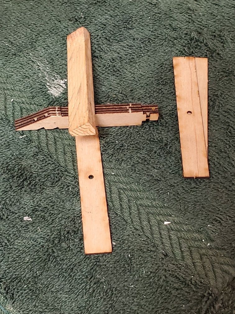
What was really driving me nuts was all those arrowhead pieces sitting loose on my workbench. Then I went back to the full sheet (first photo) and counted that there were 4 ‘sets’ of pieces at the bottom, and 2 were 5 pieces and the other box had 4 pieces. So I took my loose bits and aligned them in the order they were drawn on the sheet, figuring they had to be the 4 end beams. Eureka!

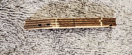
Putting them together in the right order meant there were partial holes through. And I remembered that the pieces that looked like the slopes of the hopper had holes in them - they matched the holes in the sloping ends of the composite beams.

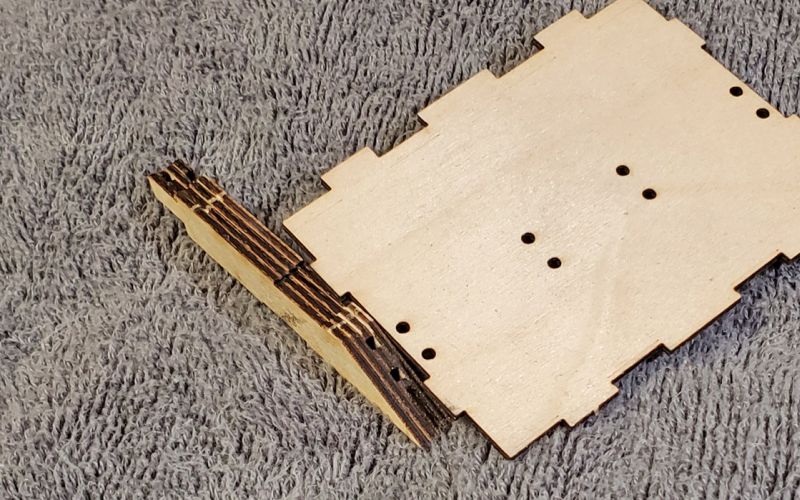
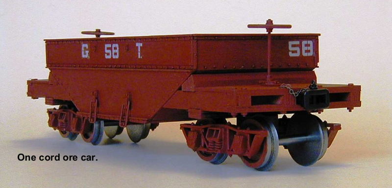
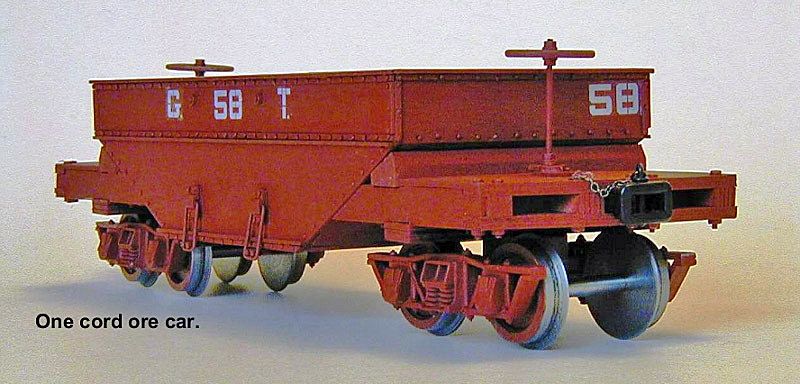
The Gilpin ore cars did not have a continuous beam lengthways - both wooden ends were bolted to the steel ore hopper. I also found some bags with lots and lots of same size nuts and bolts. Clearly I was on the right track.

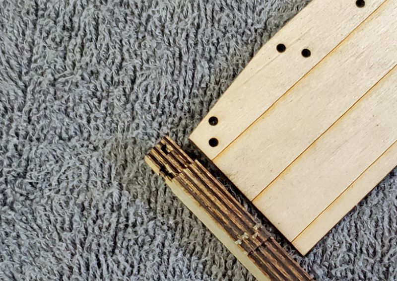
The other end of this composite beam ended up with 2 holes that matched the platform bolt-holes. The only mystery was why 4 or 5 pieces? Aha - there was one piece cut as part of the ore hopper side (so at least the model will stay in one piece and not sag, unlike the prototypes!) So all the beams are the same width when glued together. The holes for the bolts can easily be opened up once the ‘beams’ are glued.

What I need to do next is to check the length of the wagon and figure out if it is 1:19th scale, and then I can check the other sizes givin in the plans. Not that it will make much difference, as I don’t plan to make any modifications.

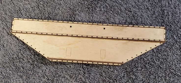
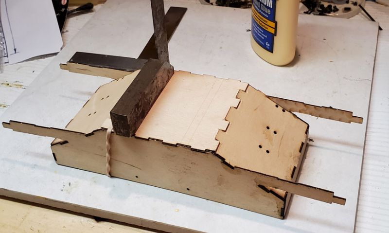
Finally, as one of the thin side pieces was already out of the sheet, I added a couple of parts - thin sprips along the top and a pair of strips are right angles pretending to be an “L” for support halfway down. I have masses of Grandt Line O scale rivets, so I decided to try them. You can just make them out olong the top and middle rows.

This thread has already paid for itself. Finding that photo has really helped! (I lightened the shadows and sharpened it in Photoshop Elements - see below.) It shows lots of details that either confirm my suspicions or show me the way forward.

You can clearly see the 5 layers of wood in the beam next to the coupler, and the bolts that hold it together (though mine will be getting glue as well.) The location of the big support crossbeam in front of the hopper is also revealed.

The metal clips holding the bottom of the hopper in place are interesting. I have some straight bits of wire that I thought would be the winding rods at the top of the hopper - you can just see some nuts up there between the writing, so maybe there’s a couple of long threaded rods somewhere.

The crossbeam supporting the truck is most enlightening. It seems to be 3 pieces of the plywood glued together. There are dozens of identical rectangles wih a central hole in the bag with the trucks, and I worked out that, with 3 of them in each fancy truck (those clearly need a couple of crosspieces - more on that later,) there were only about 1/2 dozen left, which isn’t enough for 3 planks on 2 ends of 3 wagons. There aren’t any more in the sheets so I will have to re-think. Maybe it’s time to revisit the fancy trucks.

Talking about trucks, the ones in the photo are the simple ones - no brakes, 2 sideframes and a one-piece bolster. They also seem to have 32mm gauge wheels. Hmmm . . .

I was putting the simple trucks together after painting, so I took some photos. This is the parts for the truck. There’s a little bag with top-hat bearings that fit the holes very snugly, plus a pair of bolts for holding the sideframes and a pivot bolt.

After basic painting, I bolted my trucks back together. I added a styrene washer for insulation, as the wheel center insulator does not protrude through the wheel. There were a few other issues to make it all work: the bolster is too long and needs trimming (belt sander works for this.) The bearings supplied are tight (0.125" on a 0.125" axle,) which compromises rolling if you want some flexibility for the truck. The axles are quite short in the supplied wheelsets.

On the first truck I replaced the axles with longer ones, and used 1/8" brass tubing instead of the supplied bearings. The tubing is designed to telescope and is a bit more ‘relaxed’. For the second, I was determined not to use longer axles, and I found that the ones on the wheelset would go in to the bearings. I tried to ease the bearings a little with some 320 grade emery. As the axles are short, I carefully shortened the bolster and drilled it for the bolts, not trying to make it too loose or the wheels will fall out.

Here they are lined up with a Bachmann ‘shortie’ truck from the 20’ range. Almost identical! (When I noticed that I went straight to Bachmann’s Parts store as the shorties are only $8.40 complete with wheels. Alas, they are sold out. Guess I’ll be making some more of the simple trucks.)

The other “fancy” trucks are a whole different kettle of fish. This is the contents of a bag which has more delicate sideframes, wooden bolsters, and bags of little parts. These are the rectangles with a hole in the middle, that probably go under the end frames, as mentioned previously. They are just a little wide for the metal sideframes, but nothing that sandpaper can’t fix. I will have to start counting again and see what I have.

I separated out the parts for a pair of trucks. Ther’s a bag of springs, and the small metal bits with the circular depression come in pairs for the springs. Those spring mounts had a pin on the back which corresponds (I think) to the hole in the small square plywood bits in the previous pic. You can also see the journal covers and the brake parts. The U-shapes are for the ends of the bolster.

When you start looking at the drawings to figure out how it goes together, these trucks are a very accurate model of the actual Gilpin trucks - considerably more so than the ‘simple’ ones I am using. There’s a full set of brake blocks, with a brass rod to connect them. The straight bars seem to be the end straps between the 2 sideframes over the brakes - you can see 2 little holes over where the brakes will hang. I have not found anything that would actually connect the wooden brake piece with the 2 blocks on it to the cross strap over brakes. String? Wire? There will probably be something hiding in one of the other bags. Here’s the drawing of the trucks, complete with metal bits on the ends of the bolster, brakes, etc.

The reason I decided these fancy trucks are 32mm is that, with the end cross straps roughly in place, these 32mm gauge wheels are a perfect fit. In addition, I haven’t found any bearings for the large holes in thses sideframes. So the fancy trucks are staying in the bag until I am really bored and desperate for something to fiddle with.

While taking photos of the truck parts, I also refreshed my memory on the other bits. There’s another plastic bag of stuff, including bags of nuts-and-bolts (real ones, not nbws.) There are some long threaded rods, as I vaguely recalled, which will be the winding rods for the top of the hopper. (Some chain will be needed to pull the doors back up - haven’t found any in this kit yet.) Wire, presumably for the clips that hold the hoppers closed. And a bag of brake gear, including the brake wheel, shaft, and ratchet. The triangular wood beams are supports that fit over the end frame against the hopper body.

And speaking of end beams, while I had them in my hand, I test fit them on the composite beam made from the thin plywood glued together. The rectangles are a perfect fit underneath as the cross beams for the trucks, and the triangle beam fits the depression on top. Now, what are the little V shaped cuts on the bottom for, I wonder? There’s no sign of them on the drawing above.

Progress has now been suspended until Summer 2021, as I am heading for the sunshine state and not taking it with me.

Pete Thornton said:

After completing 6 little Trail Creek 4-wheel cars (pictures later this week as I should be running them tomorrow,) I took down my next project, a bunch of Triassic Models Gilpin Ore wagons - yet another Peter Kaisan estate buy. The kit is quite interesting, so I’m posting the details for your entertainment.

A little background: Triassic is/was a UK laser-cutting kit company, and the owner, Alan, died in 2010. It was taken over by Mike (?) who is currently producing rolling stock for The Train Dept. The Gilpin Tramway is the only significant 2 ft gauge US railroad, and it was based in the gold mining area of Colorado near Victorville. The reason it was of interest to the UK guys is that they have a lot of 2’ gauge railways to model, and they use Gauge-O 32mm track at a scale of 1:19, (which is close to our 1:20.3 hence my interest in these ore wagons.) Mike indicates he can find no trace in his Triassic files of the Gilpin ore cars, but he does have the plans and files for the Gilpin caboose, which is a really cute 8-wheel car. (I told him I wanted one, but he’s pretty busy so it may be a while.) I found a photo online:

While poking around looking for a pic of the caboose, I also found a photo of the ore wagon that was made from the kit:

It’s a kit ?

It’s a kit ?

Well, yes. But it is really a bunch of parts with no instructions for making 1 or 2 or 3 ore wagons. Would you call that a “kit”?

Pete Thornton said:

It’s a kit ?

Well, yes. But it is really a bunch of parts with no instructions for making 1 or 2 or 3 ore wagons. Would you call that a “kit”?

I would, thats very interesting you building these, as a Fn2 modeler ive been planing on building a good amount of these with Devon Sinsley.

I was planning on building them fully from scratch with either a brass or resin printed ore hopper so that functional ore dumps can work.

How does one aquire these kits?

How does one aquire these kits?

A bit of luck helps. They were made by Triassic in the UK, where 2ft prototypes and 32mm gauge is common for 1:19th models, known as SM32, which is very close to Fn2.) The owner died 10 or so years ago, and they were taken over by another guy, Mike Johnson, who I have contacted. The company is now named Jurassic (http://www.summerlands-chuffer.co.uk/jurassic-models/4577586366).

Mike says he has the drawings for the Gilpin caboose, but nothing for the ore wagons. (I told him I’d take a caboose kit, but he said it will be a few years, as he’s working with Jason at The Train Dept on some kits.)

I’d like to finish the one kit I started, but the rest of the bits are up for grabs. I won’t be using the 3 or 4 pair of “fancy” trucks as they are 32mm gauge (Fn2! See above.) I have enough parts for 2 more ore wagons which you could make or use as prototypes for another type of kit? Devon has my email address if you want to chat about them.

Well here we are in 2021 and I picked up the Gilpin project again. [As an aside, I have been reading up on the Colorado & SOuthern and the other RR in CLear Creek - and the Gilpin connected with the C&S at Black Hawk. They even had some dual gauge (3’ and 2’) track.

Progress on the ore car is slow, due to the infernal rivets that need inserting and gluing in place.

This project might take a few years . . .

I could ship Kid-zilla to “help.”"

I finished one side - the O-scale rivets area bit loose in the holes, so any movement and they pop out. I ended up super-gluing them in batches of 3 so they would stay and not get lost.

I then looked at the parts and thought the sides are just cosmetic and can be applied at the end. So I started gluing a body together. The right angles were fine, and the tabs/slots were aligned in the other sloping areas, but the tabs needed to be filed to fit as the right-angle didn’t match the slope. (https://www.largescalecentral.com/externals/tinymce/plugins/emoticons/img/smiley-frown.gif).

I think the belt sander is called for. I may make the whole thing without the cosmetic sides, and do them later.

Pete, It was metal but a friend of mine placed rivets, used a piece of blue tape to hold them in place and spread JB Weld from the backside then nipped off the excess. Maybe something like that would make your “riveting” easier and keep you from gluing your fingers together with ca. (http://largescalecentral.com/externals/tinymce/plugins/emoticons/img/smiley-laughing.gif)

used a piece of blue tape to hold them in place

Tom, that is just the suggestion I was looking for. (Why didn’t I think of it??) Thank Heavan for the Forums (https://www.largescalecentral.com/externals/tinymce/plugins/emoticons/img/smiley-smile.gif)