Large Scale Central

Valve gear explanation

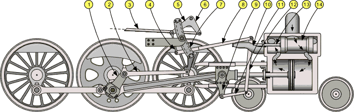
Okay I need some edification on valve gears and how they work. First off I understand the principle of valve gear. In the steam chest it reverses the flow of steam by changing the timing of the incoming steam 180 degrees. So what once was an exhaust stroke now becomes an intake stroke thus changing the stroke of the connecting rod from pulling to pushing on the drivers. I very loosely understand that. This is accomplished with eccentric rods that when set in forward push the valve rod one way thus setting the valve in the steam chest in one position. Then when the rod is moved to its other position it pulls on the valve rod into the opposite position moving the valve in the steam chest to the other position 180 degrees difference in timing.

My first assumption is when the Johnson bar is in the middle position it thus is in neutral by placing the eccentric rods in a manor that puts the steam valve in the chest in the center between the two steam openings this way they are both open which allows equal pressure on both side of the piston and also opens both steam intakes to open and the steam chest is for a lack of better words in both an exhaust and intake position so to just dump the steam out the stack without it driving the piston in either direction. Have i got this assumption right?

Now if I have all of that right, where I am still a bit fuzzy is how the Johnson bar, eccentric rods, and valve rod work in concert to accomplish all this. I get why eccentric rods are eccentric in shape. As opposed to a crank shaft and connecting rods in a car where the rod is not eccentric but rather uniform in shape and the crank is eccentric. So here is where I am stumped. What causes a perfectly round hole to wobble on a perfectly round shaft. The hole, unless I am mistaken, on the eccentric rod is round and goes on a round shaft. On a car this is true but the shaft itself is offset from center causing the motion. I don’t see how this works on a valve gear. To me nothing is happening that caues the rods to move back and forth.

Devon

I this figure #7 is the key component to reversing the valve gear direction. BTW, I have driven a real steam loco and the center position of the Johnson bar is indeed “neutral”.

The key components of Walschaerts Valve Gear:

1.Eccentric crank (UK: return crank)

2.Eccentric rod

3.Reach rod

4.Lifting link

5.Lifting arm

6.Reverse arm

7.Expansion link

8.Radius bar

9.Crosshead arm (UK Drop link)

10.Valve stem guide

11.Union link

12.Combination lever

13.Valve stem

14.Piston valve

Devon,

Notice that the Stephenson valve gear has a similar link to reverse direction.

http://www.grpc-jax.com/images/Stephensonvalvegear.avi

I get what the link DOES not not sure how. I know I am dense sometimes and have even watched videos of the link being moved. I get what it does. I guess what has me confused is how it does it and more important what is creating the rotating motion into linear back and forth motion? I get that the linkage is a precision deal that changes the orientation of the connecting rod on the axle which in turn reverses its direction. But I still do not see what is causing the elliptical motion in any direction? Nothing seems offset to me.

Devon,

let me give it a try. the eccentrics as we call them are not Concentric to the axle, they are offset by a distance. the rotational position between each pair is set when timing the locomotive, by changing the angular rotation of one or both rings. this is what sets up the motion to move the valve stem a precise and centered stroke each revolution. the Johnson bar controls another component of this motion. if centered, it balances all passageways, but rarely under steam pressure would you be on center. by effectively moving the link up and down sets the direction of travel. in either corner would be full valve travel, and bringing towards the center shortens the valve stroke.

Hope this helps

Al P.

Okay Al I think you did it. So the bearing between the rod and the axle is what is eccentric/lobed? It makes the axle off center and as it rotates its offcenternedness changes relative to the center of the rod? If thats the case then I think I get it.

Devon Sinsley said:

Okay Al I think you did it. So the bearing between the rod and the axle is what is eccentric/lobed? It makes the axle off center and as it rotates its offcenternedness changes relative to the center of the rod? If thats the case then I think I get it.

Here’s a picture worth more than 1,000 words.

As you can see, the “eccentric” is a wheel mounted & fixed eccentrically on the axle. The gear rods go backwards and forwards as the axle rotates but one is 180 deg different from the other. The reverse lever moves the valve spindle to the top or the bottom of the link, so that only one rod is having a major effect on the valve(s).

Hey guys,

Here’s another “wrinkle” to add to this discussion…in “theory”, this is how valve gear works. BUT valve gear also has two other factors which changes most of the direction of this discussion. Those factors are “lap” and “lead”. The lead is essentially the amount of movement the piston makes “before” or “after” the piston valve or slide valve starts to move. Also the “angle” of the centerlines of the afore mentioned eccentrics (forward and reverse) to each other on the axle. Pretty much how Al described it :).

Pete Thornton said:

Devon Sinsley said:

Okay Al I think you did it. So the bearing between the rod and the axle is what is eccentric/lobed? It makes the axle off center and as it rotates its offcenternedness changes relative to the center of the rod? If thats the case then I think I get it.

Here’s a picture worth more than 1,000 words.

As you can see, the “eccentric” is a wheel mounted & fixed eccentrically on the axle. The gear rods go backwards and forwards as the axle rotates but one is 180 deg different from the other. The reverse lever moves the valve spindle to the top or the bottom of the link, so that only one rod is having a major effect on the valve(s).

Thanks Pete. Al’s description along with your picture clear this up for me finally. I had not pictured, nor have seen (or at least understood what I was looking at), that the axle shaft was mount in the rod bearing off center. Add to it that you emphasize that the bearing is fixed to the axle and moves in the rod clears up how we are arriving at the eccentric motion and translating rotational movement to linear movement. You also clear up, even though I didn’t know I even needed to ask, why there are two rods. As the Johnson bar is thrown it “selects” which rod is actually driving the linkage to the valve thereby giving us the reversing direction. I hadn’t gotten that far in my inquiry but I have the answer before I had the question.

And to quote a favorite movie of mine, Cocktail, “ah light shines on marble head”, Just like that it all is crystal clear. At least in regards to valve gears.

Thanks to all for this discussion. As an innocent bystander, I’ve learned a great deal. And Pete, you underestimated the value of the picture, it’s worth at least 100,000 words, for me anyway. Not sure it would have ever clicked without the picture. Again thanks.

Dan, don’t feel left out. Steam engines and locomotives are complex pieces of hardware that is obsolete technology that we just don’t get a chance to understand unless we study it. We take for granted so many things like a steam engine and how amazing they are given when they were used. Man is a freaky genius creature. And I love to learn and modeling serves to not only produce a model but teaches me a great deal about these things I took for granted. I also love learning. My wife says that is what is wrong with my head. I have absorbed to much useless information and have not deleted enough files that it is making my head swell. She fully believes my brain cloud will rectify itself when Alzheimer’s sets in and I forget everything I knew.

Joe Zullo said:

Devon,

Notice that the Stephenson valve gear has a similar link to reverse direction.

http://www.grpc-jax.com/images/Stephensonvalvegear.avi

Joe, whats crazy (or super dense of me) is that when I watched this animation I totally missed that the axle shaft and the eccentric rod bearing were off-center of the hole in the valve rod. with Pete’s and Al’s description I went back and watched the animation again and like a flash of lightening it was painfully obvious that this was the case and was answering my question all along. This suddenly became a very good animation that explains everything I wanted to know and some things I didn’t even know I wanted to know.

I really feel ignorant (not dumb or stupid, just lacking understanding) about this thing we call a locomotive drive train. A very simple, yet amazing to me, realization is that the shaft that is driving the valve rod is set in motion by steam that is directional based on the valve position which in turn is moved by the very shaft that it is setting in motion. Now that I really understand what is going on it is a very cool and efficient design. Almost (almost) perpetual motion (except for the part that requires something to push the piston, ha ha).

My first assumption is when the Johnson bar is in the middle position it thus is in neutral by placing the eccentric rods in a manor that puts the steam valve in the chest in the center between the two steam openings this way they are both open which allows equal pressure on both side of the piston and also opens both steam intakes to open and the steam chest is for a lack of better words in both an exhaust and intake position so to just dump the steam out the stack without it driving the piston in either direction. Have i got this assumption right?

No. With the Johnson bar in the middle, the locomotive is in neutral so to speak. So the steam should not be admitted into the cylinders at all. You change when the steam admission is cut off when you move the Johnson bar form full (forward or reverse) toward center, so it cuts off the steam going into the cylinders earlier in the stroke. So with the Johnson bar dead center, the steam should be cut off all the time, but the exhausts are open.

David Maynard said:

No. With the Johnson bar in the middle, the locomotive is in neutral so to speak. So the steam should not be admitted into the cylinders at all. You change when the steam admission is cut off when you move the Johnson bar form full (forward or reverse) toward center, so it cuts off the steam going into the cylinders earlier in the stroke. So with the Johnson bar dead center, the steam should be cut off all the time, but the exhausts are open.

Okay that makes sense. Thanks for the correction.

Holy Cow, Adam. Even with my failing eye sight I can see that video clear as a bell. Thanks.

Devon Sinsley said:

Dan, don’t feel left out. Steam engines and locomotives are complex pieces of hardware that is obsolete technology that we just don’t get a chance to understand unless we study it. We take for granted so many things like a steam engine and how amazing they are given when they were used. Man is a freaky genius creature. And I love to learn and modeling serves to not only produce a model but teaches me a great deal about these things I took for granted. I also love learning. My wife says that is what is wrong with my head. I have absorbed to much useless information and have not deleted enough files that it is making my head swell. She fully believes my brain cloud will rectify itself when Alzheimer’s sets in and I forget everything I knew.

Devon, I am with you on the continuous learning. I have a healthy appetite for knowledge. If I could make a living going to school, that’s what I would be doing everyday. Its not only knowledge, but I love to learn how to build, fix, make, etc. My wife does not understand why I start so many projects just to learn how to do something new. Modeling allows me to do two things I love: learning & building or making something. And I cannot get my fill of either.

Exactly Dan

Devon,

Watch this video all the way through. It makes the steam valve operation pretty clear.

Devon and all,

I took this photo of my 1/8th scale, 1-1/2 inch per foot, Gene Allen ten-wheeler a few years ago. I had just finished some design changes to the eccentric rods going from the eccentric cams on the main axle to the eccentric link. You can see the four “cams” (mounted on the axle, 2 left and 2 right). The eccentric “cam straps” wrap around the cams causing the “wobble motion” Devon talked about. The extreme left hand cam and strap is the “forward strap” for the left hand cylinder and piston. The strap next to this is the “reverse strap” for the left hand cylinder and piston. On the extreme right is the “forward strap” for the right side cylinder and piston. The strap immediately to it’s left id the “reverse strap” for the right side cylinder and piston. Just forward of the cams and straps, you can see the four eccentric rods that attach to the valve gear “links”. One link for each cylinder. There is a “die block” which slides in a precisely machine arc in each link. the position of the die block in the slot in the link provides the amount of motion that the slide valve or piston makes inside the steam chest above the cylinder block and pistons. As you can see, when the boiler is in place over all this mechanism, it is extremely difficult to access for adjustment and maintenance. This is the main reason that Stephenson valve gear was eventually replaced by other valve gear mounted on the outside of the frame.