Large Scale Central

LED wiring for Bi-Color LEDs

I want to add bi-color LEDs to my switch panel, to show which route is good ( green ) and which route is bad ( red ). The panel is already wired with the switches to control the air solenoids for switch machine control. Wanting to add on the LEDs.

I think that this schematic will work, But I really want someone that is a whole lot smarter in electronics then me ( meaning almost everyone ) to look it over and let me know if it will work correctly. I already know full well how to let the magic smoke out of wires. What I really want is to keep it in!

AND … then I went e-baying for LEDs and they have both “Common Anode” and “Common Cathode” LEDs. Which would I need, and why?

Thanks for the help Guys.

Because you have the common lead tied to the + side of the power supply, you need common anode (this is the + side of the LED.

What I do not see is a diode to prevent the back emf from the solenoid to protect the led so a diode needs to be across the solenoid to short out the pulse that is created when power is removed from the collaspe of the magnetic field (banded end to the + feed)

Not the ideal way to do it. I wouldn’t use a current limiter but two resistors.

  1. With a fixed voltage source, the current always remains the same so a simple resistor(s) in the proper range will suffice.

  2. The two resistors would be cheaper than the current limiter.

  3. The resistors don’t care about polarity.

  4. (and “4-most” ) I use lots of common anode, Bi-color LEDs in the outdoor environment. Typically the red has one LED and the green has two LEDs within the casing. But if you run the red and green at the same current level, the red is very bright relative to the green. So you need to use a smaller resistor value for the green to get a comparable brightness to the red.

Why of course I’v changed my plans… It’s how this train thing works. Now what I want to do is add an another LED for indicating trackage direction. Much like a signaling setup, but just on the control board. Simple red, green lights showing the direction of train movement.

Like this:

I went and changed what I THINK would work, and added the location of the diode. PLEASE check to see if this will work.

Please check the location of the Diode. I went up to Mouser to order the Diodes and I haven’t a clue what to order, So some help on what I need, size wise, or whatever. A Part # would be great. The power supply is a “Radio Shack” 12VDC rated at 2.5A, But measured it reads 13.8VDC and I will have 25 of these “Switch controllers”, so I’m not sure how stable the supply is, which I think would have an effect on the choice of resistors needed if I went that way. Am I correct that the CL2N3’s would compensate for some of that fluctuation?

Thanks Guys, This Electronic stuff is my weakest link.

Hi Dave, since my electrical understanding is even less than mine, I have a question.

Will your set up actually indicate if there is a train in the block or do you set red and green manually?

It’s a manual thing. You throw the switch, and the lights and switch change. I know the board so I can instantly look and know, But others are having a problem figuring out what is going on, and How do I get the train to go where?

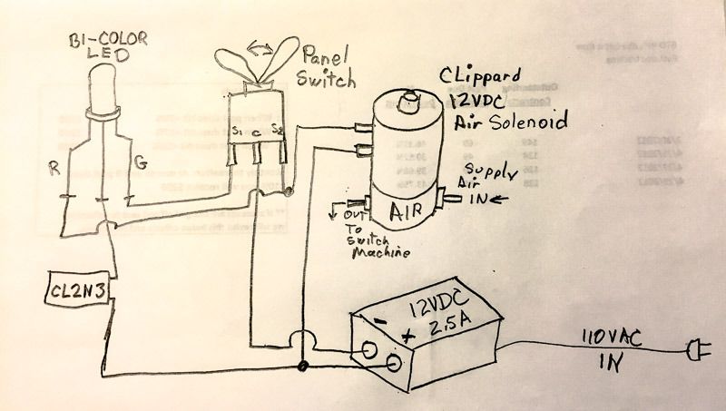
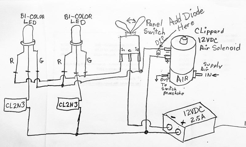
The diode would be a common rectifier diode. A 4000 series (i.e., 4001-4005) should do it, though some may say that the reverse current produced by the collapsing field could exceed 50 volts peak. A 4001 is rated for 50 volts and IIRC each subsequent value increases by 50 volts. There is no harm using a higher number (e.g., 4005 to replace a 4001).

I would still use resistors rather than current limiters. The LEDs “typically like” to run about 20 milliamps and it is easy to calculate values that will work.

There is typically a 1.5 to 2.5 volt drop across the LED. So lets use 1.5 volts as a worst case.

12 volts - 1.5 volts = 10.5 volts.

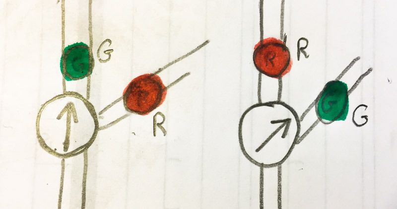
As I said, the red appears brighter than the greens and it is nice to compensate for this difference.

If we use common resistor values, we find that 620 ohm 1/4 watt is readily available and will serve for the red.

10.5 volts / 620 ohms x 1,000 = 16.9 milliamps

Also,

(10.5 volts x 10.5 volts) / 620 ohms = 0.18 watt.

And you can get 100 at just $0.04 each (10 for $0.065 each)

http://www.allelectronics.com/make-a-store/item/291-620/620-ohm-1/4-watt/1.html

And for the green, we want to push it a bit harder. Another common value in the range is 470 ohms.

10.5 volts / 470 ohms x 1,000 = 22.3 milliamps

Also,

(10.5 volts x 10.5 volts) / 470 ohms = 0.23 watts

This will brighten up the green relative to the red without unduly stressing it or anything else. Same price as the 470 ohm pieces .

http://www.allelectronics.com/make-a-store/item/291-470/470-ohm-1/4-watt/1.html

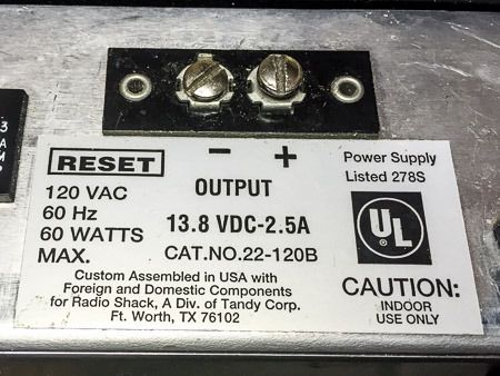
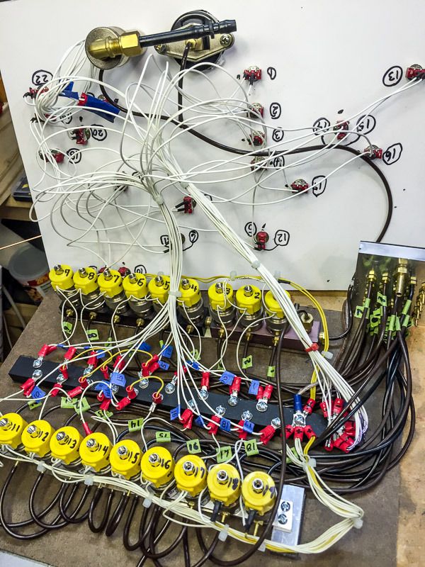
BTW, at 2.5 amps, you have plenty of power to throw 2 or maybe 3 solonoids at once, but probably no more than that if you wanted to do a diode matrix to throw groups of turnouts. I have a switch on my control panel that simultaneously throws 20 of my 21 turnouts to their “default” positions, but I use a 16 amp pack fused at 10 amps and I’m throwing LGB turnout motors that pull ~1/2 amp each.

Todd,

A couple of add ons. I have 25 of the Clippard solenoids, there rated at 10.8 to 18vdc and draw 0.056 amps, and rated for continuous use. They are only energized when the switch it thrown to the diverging route.

The LEDs are rated @ 2.0v forward and 2.4v max.

So for the red at 10v I would use a 500 ohm to get the 20milliamps ? And be using (10v x 10v )/500ohms = 0.20watts. Won’t that be running quit hot on a 1/4w resistor, since it will be on almost all the time? And if so, would a 1/2 watt be a better choice?

And for the Green side, wanting a bit brighter, 10 v / 470 ohms x 1000 =21.2 milliamps. And be using (10v x 10v) / 470 ohms = 0.21 watts.

Using 450 ohms would push it to 22.2 milliamps, and draw 0.22 watts, again would that run too hot for a 1/4 watt resistor?

Thanks for helping me figure this out.

Theoretically you are close to the wattage ratings. But I’ve found that for whatever reason, the resistors never run close to their theoretical ratings and I’ve never overheated one. If it worries you, 1/2 watt isn’t that much more $$$.

510 ohms would be closest common value to 500 ohms, but I would run the red a bit lower current at 560 or 620 to compensate for the brightness. You may want to get the LEDs and try a couple resistor values in the range and see what works best with those LEDs in that environment before ordering a bunch.

Common values:

http://www.allelectronics.com/make-a-store/category/530200/resistors/1/4-watt-resistors/1.html

Also, if you order from Allelectronics, there are many things in the catalog that you will wonder how you could ever live without. These will more than compensate for any minimum order or processing fee.

To independent resistors vs. a common cl2, the specs on the led will give brightness vs. current on the red and the green, so this can be addressed by looking at the data sheel

The cl2’s are easy to use and don’t mind differences if you change power supplies.

depending on the LED, you might use one cl2 to power both leds, again check the brightness vs. current on your LEDs

and the cost of the resistors vs. cl2s is trivial compared to the cost of the clippard solenoid. I know, I have about 30 of them

Greg

Okay, I just jumped into this thread. It dawned on me that Bi-color LEDs could be used as Headlights and Back-up lights, within a single LED. Or can they be ?

Not unless you want a Blue headlight (http://www.largescalecentral.com/externals/tinymce/plugins/emoticons/img/smiley-cool.gif)Now, Tri-Color RGB LEDs can get close to white when all three are energized. But the Bi Color Red/Green make interesting directional markers.

USA Trains used the bi colour (red/green) LEDs as class/marker lights on their F3.

You can get yellow with a red/green LED, but it is kind of orangy.

I actually do this with the eyes in the skull on the Low Rider engine mounted where the headlight was. (The headlight was “Frenched” into the front boiler door.) When the train moves forward both the red and green come on for a firely orange. In reverse, just the red comes on.

Yea, without blue, red and green make orange. You need to also have blue to end up with white.

'Scuse me. I flunked Primary Colors in elementary school. Of course you are right - it doesn’t make blue.

Daktah John, well there is a difference in additive colours and subtractive colours when we talk about primary colours. That confuses some people. With light, red, green and blue make white. With dyes/paints/pigments cyan, magenta and yellow make black.

So yous scused.

OK guys, I pulled my control panel from outside, To do so I had to disconnect all of the out going air lines to the switches. Not wanting to leave the panel out side all the time, I built a disconnect block for the air lines. This allowed me to bring the control panel into the workbench.

Well SUPPRESSES awaited me.

I hooked up the power supply ( Radio Shack 12VDC power supply)

Previously I had metered this at 13.9 VDC. Now I know that car batteries Volt out at 13.5 or such, so I wasn’t to surprised for this on a 12VDC supply. I hooked it all up on the bench, and today I metered 14.75 VDC. I’m not and electric genius, but when I turned on some solenoids and the reading went to 15.4VDC, I was puzzled at the increased voltage. Is this + voltage the power supplies way of regulating? I then measured the amp draw, and read .06 for one solenoid and .11 for two. With all on it read 1.3 amps, well within the rated draw. But with all on it read 14.5 VDC. Is this fluctuation in voltage Normal? And with as much as 2+ V sway, How do I regulate it?

Here is my control box guts, this power supply runs all of the controls, and was what I was going to use to power the LEDs also.

Am I asking to much for this supply? Or do I need to spend more $ on a separate supply for the LEDs? The Voltage range is well within the solenoids range of 10.8 to 18Vdc.

Use the CL2 instead of resistors and the power supply voltage will not matter.

If a LED is rated for 20 ma max then I would not go over this spec as it can shorten the life of the product. You can get away with over current but it only takes one to go bad at the wrong time (open house/demo).

As you suggest, the regulated voltage is higher than one would expect.

If you are sure that your volt meter is accurate, and that the power supply works to reliabily power all of the solonoids (try it for a while/extended periods), just size the resistors accordingly.

Just use 15, rather than 12 volts as your basis. A 620 ohm resistor puts you at just under 21 milliamps. You probably won’t even notice the small difference in brightness between the top and bottom of the voltage range.