Large Scale Central

Sanity Check Needed on Audio Mixer Concept

Thought maybe some of you brainy types would review my audio design concept for my Repair Shop structure and give me a “thumbs up” or a “thumbs down”. I am more of a digital guy and all this analog stuff makes my head spin. All comments appreciated.

There are two speakers in the structure, one in the machine shop area and the other in the blacksmith forge area. Each speaker is rated at 8 Ohms, 3 Watts. I have three separate audio input devices. Two are monaural sound effects generator boards – one for shop machinery and one for blacksmith sounds. These are both HQ sound modules from ITTP. http://ittproducts.com/products.html The third audio input is a stereo MP3 player called a MP3 Trigger from Sparkfun Electronics. It plays any one of 18 audio tracks contained on a micro SD card. https://www.sparkfun.com/products/11029 I have recorded 1939-era music on the card including songs from Glenn Miller, Judy Garland, Artie Shaw, and the like. There is a group of figures in the structure taking a break, sitting around the shop heater, and listening to an old 30’s style radio.

My objective is to play the machinery sound effects through the machine shop speaker, the blacksmith sound effects through the blacksmith forge speaker, and the MP3 Trigger audio tracks through both speakers. A simple control panel has toggle switches to set the sound effects cards to off, to play one time (about 60 seconds), or to loop continuously. Eighteen momentary push button switches will allow any of the 18 pre-recorded audio tracks to be played. I probably will not play sound effects and music simultaneously, but could if I wanted to.

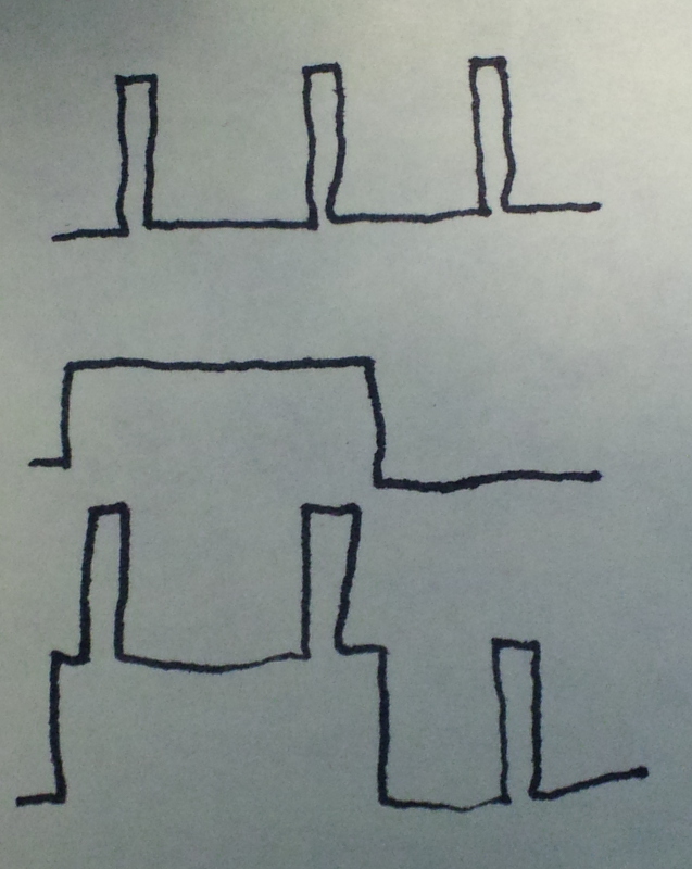
The four outputs from the three audio devices will go into a mixer circuit. The mixer combines the machinery sound effects with the left channel from the MP3 Trigger and the blacksmith sound effects with the right channel. The left and right outputs from the mixer will feed two identical audio amps. Each amp will drive one of the speakers.

The HQ sound modules have speaker outputs so I need to convert these to line level inputs for the mixer. I plan on using a resistor divider network with a 10K and a 1K resistor in series to ground. I will tap the junction between the two resistors to get the line level input. I thought about making the 1K resistor a pot for level adjustment, but the HQ board already has a volume pot onboard so this will not be needed.

The MP3 Trigger has differential line outputs designed for driving headphones. I plan on converting the differential outputs to ground referenced outputs with a resistor/capacitor network.

The four separate audio line inputs will capacitor couple into a LM3900N. This is an old 70’s - 80’s vintage op amp chip containing four independent Norton current amplifiers (very different from typical voltage amplifying op amp chips.) Two of the amplifiers will mix the left channel and the other two will mix the right channel. The left and right outputs from the 3900 will each capacitor couple into two simple audio amplifiers based on the LM386N op amp chip, with a gain of 20. Each audio amp will output about 1 Watt. The entire system will operate on 12 VDC and be contained on 3 IC chips with about 20 total resistors and 10 total capacitors (not counting the 3 commercial circuit boards.) Here is a block diagram:

What do you think? Will it work? Am I crazy?

Forget the last question … I already know the answer.

Thanks,

Bob

With all that racket going on it would drive anyone crazy.

Andrew

I don’t know how to do it at the IC component level, but your block diagram makes good sense. You have thought out the line level conversions much further than I ever did when plugging stuff together. I normally just hook it up listen for bad noises and watch for smoke!

Here is a first cut at a schematic. I decided to run the MP3 Trigger board from 5 volts rather than 12 volts like everything else. I use tiny, high-efficiency buck regulators from Pololu, so adding another is no big deal. I think I’ll breadboard it up and see if it works. The two dual pots are audio taper. If anyone sees anything outlandishly wrong, please give me a heads-up before I let the magic smoke out of the components.

Here is the link to the schematic:

http://freightsheds.largescalecentral.com/users//bob_hyman/repair_shed/Audio_Schematic.png

Bob

here is a link to a program I used back in my FM days. It’s a multi-track program that may work to simplify some of this sort of thing. I don’t remember paying for it when I got …

Goldwave

These little sound units likely have pulse width outputs and my first thought was it wouldn’t work the way you’re thinking. However, I think my first thought was wrong. If you have an analog circuit adding pulse width input, you get an added pulse width output like so:

You might want some resistor dividers and some caps to take care of dc levels, and it looks like you have them. I haven’t analyzed your schematic, Greg can do that for you, but it looks like it should do what you want.

Really need to know the ITT chip’s design, it MIGHT be a class D amplifier, but I’d guess from the age of the product line, it’s an AB, which means mixing signals should be fine.

Looking at the ITT page, it seems that they are probably using an ISD1020A, which is in the same 28 pin package. It appears to be an analog amp, but not rated 1/2 watt but 50 mw, but I’m sure the “peak” is rated higher than what the data sheet says.

http://www.tekkna.it/open2b/var/catalog/product/files/1555.pdf

The caps you have on the inputs of the LM3900 should give you DC isolation/blocking.

Then it’s just matching levels, but you addressed that.

Looks like worth a try.

Greg

Notice the noise signals on my traces. That’s ink noise, not electrical noise :smiley:

Bob: Are the 2.2uf, 0.47uf , 10uf and 470uf caps electrolytic or Polyester film caps. I am working on a similar design using a couple of different MP3 modules and an old Modeltronics chuff circuit to make an on board polyphonic sound system. I have the LM3900 and LM386 chips and most of the resistors you listed in your drawing. I was going to use trim pot instead of the audio taper pots so I could reduce the size of the parts. All of my chips and mp3 modules will be operated off 9volts which is stepped down using a couple DC to DC buck converters that will be powered off my LITH ION battery pack.

Dan S.

Dan,

I have made a few minor changes to the earlier schematic that I posted. Here is a link to the newest version currently in rework.

http://freightsheds.largescalecentral.com/users/bob_hyman/repair_shed/Rework_Layout.png

All of the capacitors are electrolytic except for the 100nf C11 and C13 which are monolythic (ceramic disk) and the 47nf C12 and C14 which are mylar. I also changed from audio taper dual pots to individual linear taper pots to save space on the circuit board. The three buck regulators have a shutdown input. This is used on the two 12 volt regulators to turn off the lights and to mute the audio. The lettered yellow circles on the schematic are I/O pins on my home-made circuit board.

Bob

Dan,

Also, here is a link to the circuit board layout for the components:

http://freightsheds.largescalecentral.com/users/bob_hyman/repair_shed/Circuit_Board.png

I added 2.2K pull-up resistors on the shutdown inputs to the two 12 volt regulators. These do not appear on the schematic.

Here is a link to the control panel layout with the controls and music selections:

http://freightsheds.largescalecentral.com/users/bob_hyman/repair_shed/Control_Panel.png

Bob

We need to teach you to use surface mount

I have one of Dave Bodner’s MP3 conversions that I can trigger with reed switches as the trains pass. It can store (IIRC) nine “banks” of 10 sounds of any length (depending on your flash drive capacity). It can also be set to play any of the nine banks in sequence or at random.

I found equipment/power tools/banging/water filling (at water tower)/brake squeal/etc. sound bites on the 'net and recorded them using the “Audacity” (free) software. I put these in one channel and the speaker is in the water tower.

Then I found sound bites of station activities such as announcements/people talking/kids/dogs barking/birds/squeaky cart wheels/etc. and recorded these onto the other track and put this speaker in the station.

The sound was prepared as a 3 minute “loop” in 30 second increments and when a train passes the reed switch, the loop will restart at any of these increments (at random) so the sound continually changes and does not become monotonous. If allowed to play through (no train passes), the unit will continue on from that track forward, restarting at #1, until it plays though the full 3 minutes at which point it stops.

Actually, four reed switches are used, one of two in the service area (selectable with one at the water tower and one at the diesel tank with separate sound banks for steam and diesel engines and their characteristic sounds), one for the freight track, and one for the passenger track that includes announcements. Any or all are selectable to any of the nine banks of sounds to be played in sequence or at random. But with trains continually coming and going, the use of all three reeds breaks up the continuity of the sound, and there is ~1 second of silence when the sound triggers. So I just select one of the four reed switches and go with that for the day.

If you are using any kind of an MP3 player, why not just mix these ITT, (and/or other sound bites that you come up with to add realism), into those tracks using the Audacity software and you won’t need to deal with a mixer because your sounds will be pre-mixed?

Thanks Bob that is helpful. I am hoping i can fit everything on a board small enough to fit in the tender with the Mp3 module , the Railboss controller and the R/C receiver and LITH ION battery pack and micro servo to operate the coupler. We will see how small I can get it.

Dan S.