Hello to all you electronic gurus.
Here is what I’m trying to do and getting confused though it should be simple. I’m building a rotary snow plow and am using a old 12volt cordless drill. I have a battery with 2 plugs pos and neg and a drill motor with 2 wires pos and neg. What I want to do is set up a switch so I can reverse the fan to spin one way or the other. I also want to control the speed. I think it would be neat to flip a switch then wind the rotary up to speed instead of starting it at full speed. I have a DPDT switch and a rheostat, what I don’t have is a clue and a wiring diagram of how to best set this up. I’m not a electronics minded guy so if someone can give me a simple explanation or point me to a diagram that would be terrific.
Thanks in advance
Todd
I think I can try to explain it. What you need is a DPDT switch with a center off. On the terminal side of the switch, your power supply wires go to the terminals in the center. the wires going to your rheostat run from the other set of terminals. From that set of terminals, you run a set of wires to the other terminals. but you reverse them on the other terminals. (it’ll form a X on the back of the DPDT switch. ) Then you run your wires from the rheostat to the motor. I don’t have a wiring diagram to show you, but I’m sure someone has one that they’ll post. Once you see the diagram, you’ll see how simple it is.
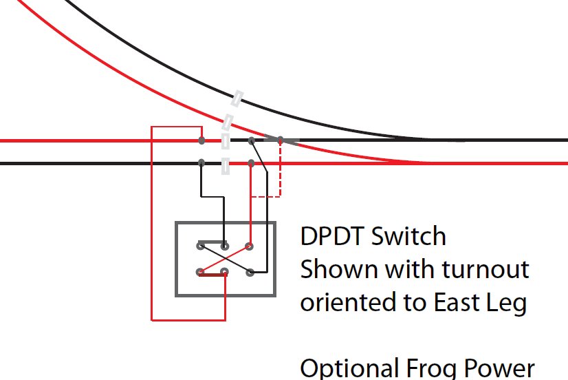
Not exactly what you are doing, but illustrates the X wiring. Note: The “Optional Frog Power” in this diagram is not correct and doesn’t work.
Jon Radder said:
Not exactly what you are doing, but illustrates the X wiring. Note: The “Optional Frog Power” in this diagram is not correct and doesn’t work.
I thought Jon might have a diagram. Just picture the wires going to the center post’s as coming from your power source. The red/black wires on the right go to your motor(or rheostat).